
- Hewlett-Packard 64-Channel Isolated Input Interrupt Module User Manual
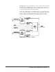
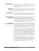
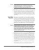
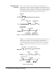
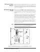
Table Of Contents
- Contents
- Warranty
- U.S. Government Restricted Rights
- WARNINGS
- Declaration of Conformity
- Chapter 1 Installing and Configuring the HP E1459A...
- Functional Description
- Configuring for Installation
- WARNING SHOCK HAZARD. Only qualified, service-trai...
- WARNING SHOCK HAZARD. When handling user wiring co...
- WARNING SHOCK HAZARD. Use wire with an insulation ...
- Caution MAXIMUM VOLTAGE. Maximum allowable voltage...
- Caution STATIC-SENSITIVE DEVICE. Use anti-static p...
- Setting the Logical Address
- Setting the Interrupt Priority
- Note Consult your mainframe manual to be sure that...
- WARNING To prevent electric shock, tighten facepla...
- WARNING To prevent the spread of fire in the case ...
- Chapter 2 Using the HP E1459A Module
- Chapter 3 HP E1459A SCPI Command Reference
- Common Command Format
- SCPI Command Format
- DIAGnostic:SYSReset Subsystem
- DISPlay:MONitor Subsystem
- INPut Subsystem
- MEASure Subsystem
- MEMory Subsystem
- SENSe Subsystem
- DAV
- NEDGe
- PEDGe
- Syntax
- [SENSe:]EVENt:PORTn:DAVailable?
- [SENSe:]EVENt:PORTn:DAVailable:ENABle
- [SENSe:]EVENt:PORTn:DAVailable:ENABle?
- [SENSe:]EVENt:PORTn:EDGE?
- [SENSe:]EVENt:PORTn:EDGE:ENABle
- [SENSe:]EVENt:PORTn:EDGE:ENABle?
- [SENSe:]EVENt:PORTn:NEDGe?
- [SENSe:]EVENt:PORTn:NEDGe:ENABle
- [SENSe:]EVENt:PORTn:NEDGe:ENABle?
- [SENSe:]EVENt:PORTn:PEDGe?
- [SENSe:]EVENt:PORTn:PEDGe:ENABle
- [SENSe:]EVENt:PORTn:PEDGe:ENABle?
- [SENSe:]EVENt:PSUMmary:DAVailable?
- [SENSe:]EVENt:PSUMmary:EDGE?
- STATus Subsystem
- Note Transition filters are always set for positiv...
- Note The Questionable Status Condition, Event, and...
- STATus:OPERation:CONDition?
- STATus:OPERation:ENABle
- STATus:OPERation:ENABle?
- STATus:OPERation[:EVENt]?
- STATus:OPERation:PSUMmary:CONDition?
- STATus:OPERation:PSUMmary:ENABle
- STATus:OPERation:PSUMmary:ENABle?
- STATus:OPERation:PSUMmary[:EVENt]?
- STATus:PRESet
- STATus:QUEStionable:CONDition?
- STATus:QUEStionable:ENABle
- STATus:QUEStionable:ENABle?
- STATus:QUEStionable[:EVENt]?
- SYSTem Subsystem
- IEEE 488.2 Common Commands
- Command Quick Reference
- Appendix A HP E1459A Specifications
- Max Input Voltage: Between High and Low terminal o...
- Module Size/Device Type: C, Register-based.
- Connectors Used: P1 and P2.
- Number of Slots: 1
- VXIbus Interface Capability: Interrupter, D16.
- Interrupt Level: 1-7, selectable.
- Power Requirements: Voltage: +5Vdc Peak Module Cur...
- Watts/Slot: 1.0
- Minimum Pulse Width: 100ms + debounce time.
- Operating Range:
- Debounce: Programmable from 16 mS to 1074 S.
- 5 Volt Supply: Output voltage : 4.5 to 5.5 V DC. M...
- Typical Time to Read 16-bit Word: 4 mS using regis...
- Terminal Module: Screw type, removable, maximum wi...
- Appendix B HP E1459A Register Definitions
- Overview
- Addressing the Registers
- The following commands are sent to the HP E1406 Co...
- When using an embedded controller VXI A16 address ...
- For example, for the HP 75000 Series C Mainframe w...
- base address (h) = (logical addressh)*40h + C000h
- For the HP E1459A, the factory-set logical address...
- base address = (90h)*(40h) + C000h> = E400h
- register address = [A16 location]h + [base addr]h ...
- The following registers can be accessed on the HP ...
- ID register (base = 00h) is a read only register. ...
- * Returns FFFFh = Hewlett-Packard A16 (only) regis...
- Device Type register (base = 02h) is a read only r...
- NOTE: Bits 8 and 9 are returned in the IACK respon...
- WRITE R = Reset to power-on state by writing a "1"...
- READ E IRQ = When "1" it indicates that an INTRX l...
- INTRX = Edge interrupt for port 0 - 3. A "1" means...
- DAVX = Data available in Port 0 - 3. A "1" means t...
- DOGENAB = "0" the watchdog timer is disabled. "1" ...
- DOGSTATE = "0" the watchdog timer is not asserted....
- For reading and writing, when BS = 0 in the Status...
- EDGE ENAB = "1" allows an edge interrupt (INTR for...
- INT/EXT = "0" data will be latched using the inter...
- DAV ENAB = "1" allows the DAV0/2 line to cause an ...
- Channels 0 through 15 are accessed when BS = 0 in ...
- Channels 32 through 47 are accessed when BS = 1 in...
- For Positive/Negative Edge Detect and Mask Registe...
- For Positive/Negative Edge Detect and Mask Registe...
- When BS = 0 in the Status/Control Register, the de...
- When BS = 1 in the Status/Control Register, the de...
- The following table lists the actual values for th...
- Register Value
- Bit pattern (hex)
- Clock Frequency
- Clock Period
- Debounce Time (4 - 4.5 clock periods)
- 2 (or 0, default)
- 0002h
- 250 kHz
- 4 mS
- 16 - 18 mS
- 3 (or 1)
- 0003h
- 125 kHz
- 8 mS
- 32 - 36 mS
- 4
- 0004h
- 62.5 kHz
- 16 mS
- 64 - 72 mS
- 5
- 0005h
- 31.25 kHz
- 32 mS
- 128 - 144 mS
- 6
- 0006h
- 15.63 kHz
- 64 mS
- 256 - 288 mS
- 7
- 0007h
- 7.81 kHz
- 128 mS
- 512 - 576 mS
- 8
- 0008h
- 3.90 kHz
- 256 mS
- 1.0 - 1.13 mS
- 9
- 0009h
- 1.95 kHz
- 512 mS
- 2.0 - 2.26 mS
- 10
- 000Ah
- 976 Hz
- 1 mS
- 4.1 - 4.6 mS
- 11
- 000Bh
- 488 Hz
- 2 mS
- 8.2 - 9.2 mS
- 12
- 000Ch
- 244 Hz
- 4.1 mS
- 16.4 - 18.4 mS
- 13
- 000Dh
- 122 Hz
- 8.2 mS
- 32.8 - 36.9 mS
- 14
- 000Eh
- 61 Hz
- 16.4 mS
- 65.5 - 73.8 mS
- 15
- 000Fh
- 30.5 Hz
- 32.8 mS
- 131 - 148 mS
- 16
- 0010h
- 15.3 Hz
- 65.5 mS
- 262 - 294 mS
- 17
- 0011h
- 7.63 Hz
- 131 mS
- 524 - 59 mS
- 18
- 0012h
- 3.82 Hz
- 262 mS
- 1.05 - 1.16 S
- 19
- 0013h
- 1.91 Hz
- 524 mS
- 2.1 - 2.36 S
- 20
- 0014h
- 0.954 Hz
- 1.05 S
- 4.2 - 4.72 S
- 21
- 0015h
- 0.477 Hz
- 2.1 S
- 8.39 - 9.43 S
- 22
- 0016h
- 0.238 Hz
- 4.2 S
- 16.8 - 18.9 S
- 23
- 0017h
- 0.119 Hz
- 8.39 S
- 33.6 - 37.8 S
- 24
- 0018h
- 60.0 mHz
- 16.8 S
- 67.1 - 75 S
- 25
- 0019h
- 30.0 mHz
- 33.6 S
- 134 - 150 S
- 26
- 001Ah
- 15.0 mHz
- 67.1 S
- 268 - 300 S
- 27
- 001Bh
- 7.5 mHz
- 134 S
- 537 - 600 S
- 28
- 001Ch
- 3.7 mHz
- 268 S
- 1074 - 1200 S
- 29
- 001Dh
- 1.9 mHz
- 537 S
- 2147 - 2400 S
- 30
- 001Eh
- 931 mHz
- 1074 S
- 4295 - 4800 S
- 31
- 001Fh
- 465.5 mHz
- 2148 S
- 8590 - 9600 S
- Command Register Port 1/3
- Command Register Port 1/3 (base + 20h)
- For reading and writing, when BS = 0 in the Status...
- EDGE ENAB = "1" allows an edge interrupt (INTR for...
- INT/EXT = "0" data will be latched using the inter...
- DAV ENAB = "1" allows the DAV1/3 line to cause an ...
- Channels 16 through 31 are accessed when BS = 0 in...
- For Positive/Negative Edge Detect and Mask Registe...
- For Positive/Negative Edge Detect and Mask Registe...
- When BS = 0 in the Status/Control Register, the de...
- Register Value
- Bit Pattern (Hex)
- Clock Frequency
- Clock Period
- Debounce Time (4 - 4.5 Clock Periods)
- 2 (or 0 ) Default
- 0002h
- 250 kHz
- 4 mS
- 16 - 18 mS
- 3 (or 1)
- 0003h
- 125 kHz
- 8 mS
- 32 - 36 mS
- 4
- 0004h
- 62.5 kHz
- 16 mS
- 64 - 72 mS
- 5
- 0005h
- 31.25 kHz
- 32 mS
- 128 - 144 mS
- 6
- 0006h
- 15.63 kHz
- 64 mS
- 256 - 288 mS
- 7
- 0007h
- 7.81 kHz
- 128 mS
- 512 - 576 mS
- 8
- 0008h
- 3.90 kHz
- 256 mS
- 1.0 - 1.13 mS
- 9
- 0009h
- 1.95 kHz
- 512 mS
- 2.0 - 2.26 mS
- 10
- 000Ah
- 976 Hz
- 1 mS
- 4.1 - 4.6 mS
- 11
- 000Bh
- 488 Hz
- 2 mS
- 8.2 - 9.2 mS
- 12
- 000Ch
- 244 Hz
- 4.1 mS
- 16.4 - 18.4 mS
- 13
- 000Dh
- 122 Hz
- 8.2 mS
- 32.8 - 36.9 mS
- 14
- 000Eh
- 61 Hz
- 16.4 mS
- 65.5 - 73.8 mS
- 15
- 000Fh
- 30.5 Hz
- 32.8 mS
- 131 - 148 mS
- 16
- 0010h
- 15.3 Hz
- 65.5 mS
- 262 - 294 mS
- 17
- 0011h
- 7.63 Hz
- 131 mS
- 524 - 590 mS
- 18
- 0012h
- 3.82 Hz
- 262 mS
- 1.05 - 1.18 S
- 19
- 0013h
- 1.91 Hz
- 524 mS
- 2.1 - 2.36 S
- 20
- 0014h
- 0.954 Hz
- 1.05 S
- 4.2 - 4.72 S
- 21
- 0015h
- 0.477 Hz
- 2.1 S
- 8.39 - 9.43 S
- 22
- 0016h
- 0.238 Hz
- 4.2 S
- 16.8 - 18.9 S
- 23
- 0017h
- 0.119 Hz
- 8.39 S
- 33.6 - 37.8 S
- 24
- 0018h
- 60 mHz
- 16.8 S
- 67.1 - 75 S
- 25
- 0019h
- 30 mHz
- 33.6 S
- 134 - 150 S
- 26
- 001Ah
- 15 mHz
- 67.1 S
- 268 - 300 S
- 27
- 001Bh
- 7.5 mHz
- 134 S
- 537 - 600 S
- 28
- 001Ch
- 3.7 mHz
- 268 S
- 1074 - 1200 S
- 29
- 001Dh
- 1.9 mHz
- 537 S
- 2147 - 2400 S
- 30
- 001Eh
- 931 mHz
- 1074 S
- 4295 - 4800 S
- 31
- 001Fh
- 466 mHz
- 2147 s
- 8590 - 9600 s
- Power On/Reset Conditions
- Programming Examples
- Appendix C Error Messages
- Index

Installing and Configuring the HP E1459A 15
Caution The user MUST ensure, based upon the programmed debounce
period and internal delays, that data to be captured has
propagated the debouncers and is fully setup prior to the
assertion of the externally generated capture clock.
The module has two primary modes of operation: the module can interrupt
your software when an event occurs or your software can periodically poll
the module to determine if an event has occurred. If the channel data
registers are serviced via a "polled mode" method (which is not keyed to the
posting of the "marker bits" or the occurrence of an interrupt), no timing
relationship will necessarily exist with the debounced event. As a result, a
small window of uncertainty exists between input latch timing and debounce
circuit timing.
Input Edge
Detection
Each channel may be programmed to sense the occurrence of a qualified
edge transition of either polarity, or both concurrently. All channels are
preprocessed via the debounce circuits before presentation to the edge detect
logic. Edge detection is performed (by sampling methods) within each of the
four ports, in groups of 16 channels per port. If enabled, each port will post
an "Edge Interrupt Marker" to the control logic circuitry on the occurrence
of a qualified edge event for any active channel within its channel group.
(The static state of these markers may be tested via the "Edge Interrupt
Status Register." These markers are also accessible at the front panel.)
Caution Edge Detect Markers are cleared by a read of the register
causing the marker to be posted. Since there is no high-level
method of determining whether a positive or negative edge
event is generating the marker, both edge detect registers
(positive and negative) within a channel group, MUST be read
during the service interval to identify ALL edge events which
may have potentially occurred.
Each marker bit is forced inactive for a two clock (16 MHz) periods each
time either edge detect register is read. (The edge detect register is then
cleared at the end of the cycle.) If the register that is not being read is inactive
and remains inactive, the marker will continue to remain inactive. If the
register that is not read is active or becomes active, the marker is again
posted to the "control" logic. The control logic detects this event and stores
this occurrence in a flip-flop which marks the pending need for service. If
this marking register, (now active), is then read and ultimately cleared, the
marker will become inactive and will remain inactive until the subsequent
occurrence of another qualified edge event. The control logic detects this
"cleared marker condition" and consequently clears the pending service
request flip-flop.
External edge events which occur concurrently with a register read/clear
cycle are queued and post-processed on completion of the cycle.