
- Hewlett-Packard 64-Channel Isolated Input Interrupt Module User Manual


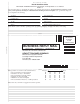

Table Of Contents
- Contents
- Warranty
- U.S. Government Restricted Rights
- WARNINGS
- Declaration of Conformity
- Chapter 1 Installing and Configuring the HP E1459A...
- Functional Description
- Configuring for Installation
- WARNING SHOCK HAZARD. Only qualified, service-trai...
- WARNING SHOCK HAZARD. When handling user wiring co...
- WARNING SHOCK HAZARD. Use wire with an insulation ...
- Caution MAXIMUM VOLTAGE. Maximum allowable voltage...
- Caution STATIC-SENSITIVE DEVICE. Use anti-static p...
- Setting the Logical Address
- Setting the Interrupt Priority
- Note Consult your mainframe manual to be sure that...
- WARNING To prevent electric shock, tighten facepla...
- WARNING To prevent the spread of fire in the case ...
- Chapter 2 Using the HP E1459A Module
- Chapter 3 HP E1459A SCPI Command Reference
- Common Command Format
- SCPI Command Format
- DIAGnostic:SYSReset Subsystem
- DISPlay:MONitor Subsystem
- INPut Subsystem
- MEASure Subsystem
- MEMory Subsystem
- SENSe Subsystem
- DAV
- NEDGe
- PEDGe
- Syntax
- [SENSe:]EVENt:PORTn:DAVailable?
- [SENSe:]EVENt:PORTn:DAVailable:ENABle
- [SENSe:]EVENt:PORTn:DAVailable:ENABle?
- [SENSe:]EVENt:PORTn:EDGE?
- [SENSe:]EVENt:PORTn:EDGE:ENABle
- [SENSe:]EVENt:PORTn:EDGE:ENABle?
- [SENSe:]EVENt:PORTn:NEDGe?
- [SENSe:]EVENt:PORTn:NEDGe:ENABle
- [SENSe:]EVENt:PORTn:NEDGe:ENABle?
- [SENSe:]EVENt:PORTn:PEDGe?
- [SENSe:]EVENt:PORTn:PEDGe:ENABle
- [SENSe:]EVENt:PORTn:PEDGe:ENABle?
- [SENSe:]EVENt:PSUMmary:DAVailable?
- [SENSe:]EVENt:PSUMmary:EDGE?
- STATus Subsystem
- Note Transition filters are always set for positiv...
- Note The Questionable Status Condition, Event, and...
- STATus:OPERation:CONDition?
- STATus:OPERation:ENABle
- STATus:OPERation:ENABle?
- STATus:OPERation[:EVENt]?
- STATus:OPERation:PSUMmary:CONDition?
- STATus:OPERation:PSUMmary:ENABle
- STATus:OPERation:PSUMmary:ENABle?
- STATus:OPERation:PSUMmary[:EVENt]?
- STATus:PRESet
- STATus:QUEStionable:CONDition?
- STATus:QUEStionable:ENABle
- STATus:QUEStionable:ENABle?
- STATus:QUEStionable[:EVENt]?
- SYSTem Subsystem
- IEEE 488.2 Common Commands
- Command Quick Reference
- Appendix A HP E1459A Specifications
- Max Input Voltage: Between High and Low terminal o...
- Module Size/Device Type: C, Register-based.
- Connectors Used: P1 and P2.
- Number of Slots: 1
- VXIbus Interface Capability: Interrupter, D16.
- Interrupt Level: 1-7, selectable.
- Power Requirements: Voltage: +5Vdc Peak Module Cur...
- Watts/Slot: 1.0
- Minimum Pulse Width: 100ms + debounce time.
- Operating Range:
- Debounce: Programmable from 16 mS to 1074 S.
- 5 Volt Supply: Output voltage : 4.5 to 5.5 V DC. M...
- Typical Time to Read 16-bit Word: 4 mS using regis...
- Terminal Module: Screw type, removable, maximum wi...
- Appendix B HP E1459A Register Definitions
- Overview
- Addressing the Registers
- The following commands are sent to the HP E1406 Co...
- When using an embedded controller VXI A16 address ...
- For example, for the HP 75000 Series C Mainframe w...
- base address (h) = (logical addressh)*40h + C000h
- For the HP E1459A, the factory-set logical address...
- base address = (90h)*(40h) + C000h> = E400h
- register address = [A16 location]h + [base addr]h ...
- The following registers can be accessed on the HP ...
- ID register (base = 00h) is a read only register. ...
- * Returns FFFFh = Hewlett-Packard A16 (only) regis...
- Device Type register (base = 02h) is a read only r...
- NOTE: Bits 8 and 9 are returned in the IACK respon...
- WRITE R = Reset to power-on state by writing a "1"...
- READ E IRQ = When "1" it indicates that an INTRX l...
- INTRX = Edge interrupt for port 0 - 3. A "1" means...
- DAVX = Data available in Port 0 - 3. A "1" means t...
- DOGENAB = "0" the watchdog timer is disabled. "1" ...
- DOGSTATE = "0" the watchdog timer is not asserted....
- For reading and writing, when BS = 0 in the Status...
- EDGE ENAB = "1" allows an edge interrupt (INTR for...
- INT/EXT = "0" data will be latched using the inter...
- DAV ENAB = "1" allows the DAV0/2 line to cause an ...
- Channels 0 through 15 are accessed when BS = 0 in ...
- Channels 32 through 47 are accessed when BS = 1 in...
- For Positive/Negative Edge Detect and Mask Registe...
- For Positive/Negative Edge Detect and Mask Registe...
- When BS = 0 in the Status/Control Register, the de...
- When BS = 1 in the Status/Control Register, the de...
- The following table lists the actual values for th...
- Register Value
- Bit pattern (hex)
- Clock Frequency
- Clock Period
- Debounce Time (4 - 4.5 clock periods)
- 2 (or 0, default)
- 0002h
- 250 kHz
- 4 mS
- 16 - 18 mS
- 3 (or 1)
- 0003h
- 125 kHz
- 8 mS
- 32 - 36 mS
- 4
- 0004h
- 62.5 kHz
- 16 mS
- 64 - 72 mS
- 5
- 0005h
- 31.25 kHz
- 32 mS
- 128 - 144 mS
- 6
- 0006h
- 15.63 kHz
- 64 mS
- 256 - 288 mS
- 7
- 0007h
- 7.81 kHz
- 128 mS
- 512 - 576 mS
- 8
- 0008h
- 3.90 kHz
- 256 mS
- 1.0 - 1.13 mS
- 9
- 0009h
- 1.95 kHz
- 512 mS
- 2.0 - 2.26 mS
- 10
- 000Ah
- 976 Hz
- 1 mS
- 4.1 - 4.6 mS
- 11
- 000Bh
- 488 Hz
- 2 mS
- 8.2 - 9.2 mS
- 12
- 000Ch
- 244 Hz
- 4.1 mS
- 16.4 - 18.4 mS
- 13
- 000Dh
- 122 Hz
- 8.2 mS
- 32.8 - 36.9 mS
- 14
- 000Eh
- 61 Hz
- 16.4 mS
- 65.5 - 73.8 mS
- 15
- 000Fh
- 30.5 Hz
- 32.8 mS
- 131 - 148 mS
- 16
- 0010h
- 15.3 Hz
- 65.5 mS
- 262 - 294 mS
- 17
- 0011h
- 7.63 Hz
- 131 mS
- 524 - 59 mS
- 18
- 0012h
- 3.82 Hz
- 262 mS
- 1.05 - 1.16 S
- 19
- 0013h
- 1.91 Hz
- 524 mS
- 2.1 - 2.36 S
- 20
- 0014h
- 0.954 Hz
- 1.05 S
- 4.2 - 4.72 S
- 21
- 0015h
- 0.477 Hz
- 2.1 S
- 8.39 - 9.43 S
- 22
- 0016h
- 0.238 Hz
- 4.2 S
- 16.8 - 18.9 S
- 23
- 0017h
- 0.119 Hz
- 8.39 S
- 33.6 - 37.8 S
- 24
- 0018h
- 60.0 mHz
- 16.8 S
- 67.1 - 75 S
- 25
- 0019h
- 30.0 mHz
- 33.6 S
- 134 - 150 S
- 26
- 001Ah
- 15.0 mHz
- 67.1 S
- 268 - 300 S
- 27
- 001Bh
- 7.5 mHz
- 134 S
- 537 - 600 S
- 28
- 001Ch
- 3.7 mHz
- 268 S
- 1074 - 1200 S
- 29
- 001Dh
- 1.9 mHz
- 537 S
- 2147 - 2400 S
- 30
- 001Eh
- 931 mHz
- 1074 S
- 4295 - 4800 S
- 31
- 001Fh
- 465.5 mHz
- 2148 S
- 8590 - 9600 S
- Command Register Port 1/3
- Command Register Port 1/3 (base + 20h)
- For reading and writing, when BS = 0 in the Status...
- EDGE ENAB = "1" allows an edge interrupt (INTR for...
- INT/EXT = "0" data will be latched using the inter...
- DAV ENAB = "1" allows the DAV1/3 line to cause an ...
- Channels 16 through 31 are accessed when BS = 0 in...
- For Positive/Negative Edge Detect and Mask Registe...
- For Positive/Negative Edge Detect and Mask Registe...
- When BS = 0 in the Status/Control Register, the de...
- Register Value
- Bit Pattern (Hex)
- Clock Frequency
- Clock Period
- Debounce Time (4 - 4.5 Clock Periods)
- 2 (or 0 ) Default
- 0002h
- 250 kHz
- 4 mS
- 16 - 18 mS
- 3 (or 1)
- 0003h
- 125 kHz
- 8 mS
- 32 - 36 mS
- 4
- 0004h
- 62.5 kHz
- 16 mS
- 64 - 72 mS
- 5
- 0005h
- 31.25 kHz
- 32 mS
- 128 - 144 mS
- 6
- 0006h
- 15.63 kHz
- 64 mS
- 256 - 288 mS
- 7
- 0007h
- 7.81 kHz
- 128 mS
- 512 - 576 mS
- 8
- 0008h
- 3.90 kHz
- 256 mS
- 1.0 - 1.13 mS
- 9
- 0009h
- 1.95 kHz
- 512 mS
- 2.0 - 2.26 mS
- 10
- 000Ah
- 976 Hz
- 1 mS
- 4.1 - 4.6 mS
- 11
- 000Bh
- 488 Hz
- 2 mS
- 8.2 - 9.2 mS
- 12
- 000Ch
- 244 Hz
- 4.1 mS
- 16.4 - 18.4 mS
- 13
- 000Dh
- 122 Hz
- 8.2 mS
- 32.8 - 36.9 mS
- 14
- 000Eh
- 61 Hz
- 16.4 mS
- 65.5 - 73.8 mS
- 15
- 000Fh
- 30.5 Hz
- 32.8 mS
- 131 - 148 mS
- 16
- 0010h
- 15.3 Hz
- 65.5 mS
- 262 - 294 mS
- 17
- 0011h
- 7.63 Hz
- 131 mS
- 524 - 590 mS
- 18
- 0012h
- 3.82 Hz
- 262 mS
- 1.05 - 1.18 S
- 19
- 0013h
- 1.91 Hz
- 524 mS
- 2.1 - 2.36 S
- 20
- 0014h
- 0.954 Hz
- 1.05 S
- 4.2 - 4.72 S
- 21
- 0015h
- 0.477 Hz
- 2.1 S
- 8.39 - 9.43 S
- 22
- 0016h
- 0.238 Hz
- 4.2 S
- 16.8 - 18.9 S
- 23
- 0017h
- 0.119 Hz
- 8.39 S
- 33.6 - 37.8 S
- 24
- 0018h
- 60 mHz
- 16.8 S
- 67.1 - 75 S
- 25
- 0019h
- 30 mHz
- 33.6 S
- 134 - 150 S
- 26
- 001Ah
- 15 mHz
- 67.1 S
- 268 - 300 S
- 27
- 001Bh
- 7.5 mHz
- 134 S
- 537 - 600 S
- 28
- 001Ch
- 3.7 mHz
- 268 S
- 1074 - 1200 S
- 29
- 001Dh
- 1.9 mHz
- 537 S
- 2147 - 2400 S
- 30
- 001Eh
- 931 mHz
- 1074 S
- 4295 - 4800 S
- 31
- 001Fh
- 466 mHz
- 2147 s
- 8590 - 9600 s
- Power On/Reset Conditions
- Programming Examples
- Appendix C Error Messages
- Index

Contents 3
STATus:QUEStionable:CONDition? ................................................................. 66
STATus:QUEStionable:ENABle <mask> ..........................................................66
STATus:QUEStionable:ENABle? ......................................................................67
STATus:QUEStionable[:EVENt]? ......................................................................67
SYSTem Subsystem ................................................................................................... 68
SYSTem:CDEScription? <number> ................................................................... 68
SYSTem:CTYPe? <number> .............................................................................. 68
SYSTem:ERRor? ................................................................................................ 69
SYSTem:VERSion? ............................................................................................ 69
IEEE 488.2 Common Commands...............................................................................70
Command Quick Reference........................................................................................71
Appendix A
HP E1459A Specifications ...........................................................................................73
Appendix B
HP E1459A Register Definitions ................................................................................75
Overview.....................................................................................................................75
Addressing the Registers ............................................................................................ 76
Register Access with Logical Address ................................................................76
Register Access with Memory Mapping .............................................................76
Register Definitions .................................................................................................... 77
Manufacturer ID Register ....................................................................................78
Device Type Register .......................................................................................... 78
Status/Control Register ....................................................................................... 78
Edge Interrupt Status Register .............................................................................80
Data Available Status Register ............................................................................ 80
Watchdog Timer Control/Status Register ...........................................................81
Command Register Port 0/2 ................................................................................81
Channel Data Register Port 0/2 ........................................................................... 83
Positive Edge Detect Register Port 0/2 ............................................................... 83
Negative Edge Detect Register Port 0/2 ..............................................................84
Positive Mask Register Port 0/2 .......................................................................... 84
Negative Mask Register Port 0/2 ........................................................................ 84
Debounce Clock Register Port 0 and Port1/ Port 2 and Port 3 ........................... 85
Command Register Port 1/3 ................................................................................86
Channel Data Register Port 1/3 ........................................................................... 87
Positive Edge Detect Register Port 1/3 ............................................................... 88
Negative Edge Detect Register Port 1/3 ..............................................................88
Positive Mask Register Port 1/3 .......................................................................... 88
Negative Mask Register Port 1/3 ........................................................................ 89
Debounce Clock Register Port 0 and Port 1/ Port 2 and Port 3 .......................... 89
Power On/Reset Conditions........................................................................................ 91
Programming Examples.............................................................................................. 91
Output and Edge Detection Examples ................................................................ 92
Appendix C
Error Messages ..........................................................................................................105