
- Hewlett-Packard 64-Channel Isolated Input Interrupt Module User Manual
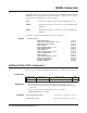
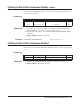
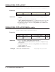

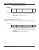
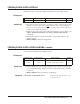

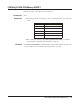
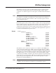
Table Of Contents
- Contents
- Warranty
- U.S. Government Restricted Rights
- WARNINGS
- Declaration of Conformity
- Chapter 1 Installing and Configuring the HP E1459A...
- Functional Description
- Configuring for Installation
- WARNING SHOCK HAZARD. Only qualified, service-trai...
- WARNING SHOCK HAZARD. When handling user wiring co...
- WARNING SHOCK HAZARD. Use wire with an insulation ...
- Caution MAXIMUM VOLTAGE. Maximum allowable voltage...
- Caution STATIC-SENSITIVE DEVICE. Use anti-static p...
- Setting the Logical Address
- Setting the Interrupt Priority
- Note Consult your mainframe manual to be sure that...
- WARNING To prevent electric shock, tighten facepla...
- WARNING To prevent the spread of fire in the case ...
- Chapter 2 Using the HP E1459A Module
- Chapter 3 HP E1459A SCPI Command Reference
- Common Command Format
- SCPI Command Format
- DIAGnostic:SYSReset Subsystem
- DISPlay:MONitor Subsystem
- INPut Subsystem
- MEASure Subsystem
- MEMory Subsystem
- SENSe Subsystem
- DAV
- NEDGe
- PEDGe
- Syntax
- [SENSe:]EVENt:PORTn:DAVailable?
- [SENSe:]EVENt:PORTn:DAVailable:ENABle
- [SENSe:]EVENt:PORTn:DAVailable:ENABle?
- [SENSe:]EVENt:PORTn:EDGE?
- [SENSe:]EVENt:PORTn:EDGE:ENABle
- [SENSe:]EVENt:PORTn:EDGE:ENABle?
- [SENSe:]EVENt:PORTn:NEDGe?
- [SENSe:]EVENt:PORTn:NEDGe:ENABle
- [SENSe:]EVENt:PORTn:NEDGe:ENABle?
- [SENSe:]EVENt:PORTn:PEDGe?
- [SENSe:]EVENt:PORTn:PEDGe:ENABle
- [SENSe:]EVENt:PORTn:PEDGe:ENABle?
- [SENSe:]EVENt:PSUMmary:DAVailable?
- [SENSe:]EVENt:PSUMmary:EDGE?
- STATus Subsystem
- Note Transition filters are always set for positiv...
- Note The Questionable Status Condition, Event, and...
- STATus:OPERation:CONDition?
- STATus:OPERation:ENABle
- STATus:OPERation:ENABle?
- STATus:OPERation[:EVENt]?
- STATus:OPERation:PSUMmary:CONDition?
- STATus:OPERation:PSUMmary:ENABle
- STATus:OPERation:PSUMmary:ENABle?
- STATus:OPERation:PSUMmary[:EVENt]?
- STATus:PRESet
- STATus:QUEStionable:CONDition?
- STATus:QUEStionable:ENABle
- STATus:QUEStionable:ENABle?
- STATus:QUEStionable[:EVENt]?
- SYSTem Subsystem
- IEEE 488.2 Common Commands
- Command Quick Reference
- Appendix A HP E1459A Specifications
- Max Input Voltage: Between High and Low terminal o...
- Module Size/Device Type: C, Register-based.
- Connectors Used: P1 and P2.
- Number of Slots: 1
- VXIbus Interface Capability: Interrupter, D16.
- Interrupt Level: 1-7, selectable.
- Power Requirements: Voltage: +5Vdc Peak Module Cur...
- Watts/Slot: 1.0
- Minimum Pulse Width: 100ms + debounce time.
- Operating Range:
- Debounce: Programmable from 16 mS to 1074 S.
- 5 Volt Supply: Output voltage : 4.5 to 5.5 V DC. M...
- Typical Time to Read 16-bit Word: 4 mS using regis...
- Terminal Module: Screw type, removable, maximum wi...
- Appendix B HP E1459A Register Definitions
- Overview
- Addressing the Registers
- The following commands are sent to the HP E1406 Co...
- When using an embedded controller VXI A16 address ...
- For example, for the HP 75000 Series C Mainframe w...
- base address (h) = (logical addressh)*40h + C000h
- For the HP E1459A, the factory-set logical address...
- base address = (90h)*(40h) + C000h> = E400h
- register address = [A16 location]h + [base addr]h ...
- The following registers can be accessed on the HP ...
- ID register (base = 00h) is a read only register. ...
- * Returns FFFFh = Hewlett-Packard A16 (only) regis...
- Device Type register (base = 02h) is a read only r...
- NOTE: Bits 8 and 9 are returned in the IACK respon...
- WRITE R = Reset to power-on state by writing a "1"...
- READ E IRQ = When "1" it indicates that an INTRX l...
- INTRX = Edge interrupt for port 0 - 3. A "1" means...
- DAVX = Data available in Port 0 - 3. A "1" means t...
- DOGENAB = "0" the watchdog timer is disabled. "1" ...
- DOGSTATE = "0" the watchdog timer is not asserted....
- For reading and writing, when BS = 0 in the Status...
- EDGE ENAB = "1" allows an edge interrupt (INTR for...
- INT/EXT = "0" data will be latched using the inter...
- DAV ENAB = "1" allows the DAV0/2 line to cause an ...
- Channels 0 through 15 are accessed when BS = 0 in ...
- Channels 32 through 47 are accessed when BS = 1 in...
- For Positive/Negative Edge Detect and Mask Registe...
- For Positive/Negative Edge Detect and Mask Registe...
- When BS = 0 in the Status/Control Register, the de...
- When BS = 1 in the Status/Control Register, the de...
- The following table lists the actual values for th...
- Register Value
- Bit pattern (hex)
- Clock Frequency
- Clock Period
- Debounce Time (4 - 4.5 clock periods)
- 2 (or 0, default)
- 0002h
- 250 kHz
- 4 mS
- 16 - 18 mS
- 3 (or 1)
- 0003h
- 125 kHz
- 8 mS
- 32 - 36 mS
- 4
- 0004h
- 62.5 kHz
- 16 mS
- 64 - 72 mS
- 5
- 0005h
- 31.25 kHz
- 32 mS
- 128 - 144 mS
- 6
- 0006h
- 15.63 kHz
- 64 mS
- 256 - 288 mS
- 7
- 0007h
- 7.81 kHz
- 128 mS
- 512 - 576 mS
- 8
- 0008h
- 3.90 kHz
- 256 mS
- 1.0 - 1.13 mS
- 9
- 0009h
- 1.95 kHz
- 512 mS
- 2.0 - 2.26 mS
- 10
- 000Ah
- 976 Hz
- 1 mS
- 4.1 - 4.6 mS
- 11
- 000Bh
- 488 Hz
- 2 mS
- 8.2 - 9.2 mS
- 12
- 000Ch
- 244 Hz
- 4.1 mS
- 16.4 - 18.4 mS
- 13
- 000Dh
- 122 Hz
- 8.2 mS
- 32.8 - 36.9 mS
- 14
- 000Eh
- 61 Hz
- 16.4 mS
- 65.5 - 73.8 mS
- 15
- 000Fh
- 30.5 Hz
- 32.8 mS
- 131 - 148 mS
- 16
- 0010h
- 15.3 Hz
- 65.5 mS
- 262 - 294 mS
- 17
- 0011h
- 7.63 Hz
- 131 mS
- 524 - 59 mS
- 18
- 0012h
- 3.82 Hz
- 262 mS
- 1.05 - 1.16 S
- 19
- 0013h
- 1.91 Hz
- 524 mS
- 2.1 - 2.36 S
- 20
- 0014h
- 0.954 Hz
- 1.05 S
- 4.2 - 4.72 S
- 21
- 0015h
- 0.477 Hz
- 2.1 S
- 8.39 - 9.43 S
- 22
- 0016h
- 0.238 Hz
- 4.2 S
- 16.8 - 18.9 S
- 23
- 0017h
- 0.119 Hz
- 8.39 S
- 33.6 - 37.8 S
- 24
- 0018h
- 60.0 mHz
- 16.8 S
- 67.1 - 75 S
- 25
- 0019h
- 30.0 mHz
- 33.6 S
- 134 - 150 S
- 26
- 001Ah
- 15.0 mHz
- 67.1 S
- 268 - 300 S
- 27
- 001Bh
- 7.5 mHz
- 134 S
- 537 - 600 S
- 28
- 001Ch
- 3.7 mHz
- 268 S
- 1074 - 1200 S
- 29
- 001Dh
- 1.9 mHz
- 537 S
- 2147 - 2400 S
- 30
- 001Eh
- 931 mHz
- 1074 S
- 4295 - 4800 S
- 31
- 001Fh
- 465.5 mHz
- 2148 S
- 8590 - 9600 S
- Command Register Port 1/3
- Command Register Port 1/3 (base + 20h)
- For reading and writing, when BS = 0 in the Status...
- EDGE ENAB = "1" allows an edge interrupt (INTR for...
- INT/EXT = "0" data will be latched using the inter...
- DAV ENAB = "1" allows the DAV1/3 line to cause an ...
- Channels 16 through 31 are accessed when BS = 0 in...
- For Positive/Negative Edge Detect and Mask Registe...
- For Positive/Negative Edge Detect and Mask Registe...
- When BS = 0 in the Status/Control Register, the de...
- Register Value
- Bit Pattern (Hex)
- Clock Frequency
- Clock Period
- Debounce Time (4 - 4.5 Clock Periods)
- 2 (or 0 ) Default
- 0002h
- 250 kHz
- 4 mS
- 16 - 18 mS
- 3 (or 1)
- 0003h
- 125 kHz
- 8 mS
- 32 - 36 mS
- 4
- 0004h
- 62.5 kHz
- 16 mS
- 64 - 72 mS
- 5
- 0005h
- 31.25 kHz
- 32 mS
- 128 - 144 mS
- 6
- 0006h
- 15.63 kHz
- 64 mS
- 256 - 288 mS
- 7
- 0007h
- 7.81 kHz
- 128 mS
- 512 - 576 mS
- 8
- 0008h
- 3.90 kHz
- 256 mS
- 1.0 - 1.13 mS
- 9
- 0009h
- 1.95 kHz
- 512 mS
- 2.0 - 2.26 mS
- 10
- 000Ah
- 976 Hz
- 1 mS
- 4.1 - 4.6 mS
- 11
- 000Bh
- 488 Hz
- 2 mS
- 8.2 - 9.2 mS
- 12
- 000Ch
- 244 Hz
- 4.1 mS
- 16.4 - 18.4 mS
- 13
- 000Dh
- 122 Hz
- 8.2 mS
- 32.8 - 36.9 mS
- 14
- 000Eh
- 61 Hz
- 16.4 mS
- 65.5 - 73.8 mS
- 15
- 000Fh
- 30.5 Hz
- 32.8 mS
- 131 - 148 mS
- 16
- 0010h
- 15.3 Hz
- 65.5 mS
- 262 - 294 mS
- 17
- 0011h
- 7.63 Hz
- 131 mS
- 524 - 590 mS
- 18
- 0012h
- 3.82 Hz
- 262 mS
- 1.05 - 1.18 S
- 19
- 0013h
- 1.91 Hz
- 524 mS
- 2.1 - 2.36 S
- 20
- 0014h
- 0.954 Hz
- 1.05 S
- 4.2 - 4.72 S
- 21
- 0015h
- 0.477 Hz
- 2.1 S
- 8.39 - 9.43 S
- 22
- 0016h
- 0.238 Hz
- 4.2 S
- 16.8 - 18.9 S
- 23
- 0017h
- 0.119 Hz
- 8.39 S
- 33.6 - 37.8 S
- 24
- 0018h
- 60 mHz
- 16.8 S
- 67.1 - 75 S
- 25
- 0019h
- 30 mHz
- 33.6 S
- 134 - 150 S
- 26
- 001Ah
- 15 mHz
- 67.1 S
- 268 - 300 S
- 27
- 001Bh
- 7.5 mHz
- 134 S
- 537 - 600 S
- 28
- 001Ch
- 3.7 mHz
- 268 S
- 1074 - 1200 S
- 29
- 001Dh
- 1.9 mHz
- 537 S
- 2147 - 2400 S
- 30
- 001Eh
- 931 mHz
- 1074 S
- 4295 - 4800 S
- 31
- 001Fh
- 466 mHz
- 2147 s
- 8590 - 9600 s
- Power On/Reset Conditions
- Programming Examples
- Appendix C Error Messages
- Index

60 HP E1459A SCPI Command Reference
STATus Subsystem
The STATus subsystem controls the SCPI-defined Operation and Questionable
Status registers, Standard Event register, and the Status Byte register. Each is
comprised of a condition register, an event register, an enable mask, and transition
filters.
Note Transition filters are always set for positive edge transitions. When an event occurs,
the condition is set and the event register bit is set true. If the event condition is
cleared, the event status register remains set. The event status register is cleared
upon reading that register.
Each status register works as follows: when a condition occurs, the appropriate bit
in the condition register is set or cleared. The contents of the events register and the
enable mask are logically ANDed bit-for-bit; if any bit of the result is set, the
summary bit for that register is set in the status byte. The status byte summary bit for
the Operation status register is bit 7; for the Questionable Signal status register, bit
3; and for the Standard Event registers is bit 5.
Syntax STATus
:OPERation
:CONDition? page 62
:ENABle <
mask
> page 62
:ENABle? page 63
[:EVENt]? page 63
:PSUMmary:CONDition? page 63
:PSUMmary:ENABle <
mask
> page 64
:PSUMmary:ENABle? page 64
:PSUMmary[:EVENt]? page 65
:PRESet page 65
:QUEStionable
:CONDition? page 66
:ENABle <
mask
> page 66
:ENABle? page 67
[:EVENt]? page 67
The STATus system contains five registers, two of which are under IEEE 488.2
control: the Event Status Register (*ESE?) and the Status Byte Register (*STB?).
The Operational Status bit (OPR), Service Request bit (RQS), Event Summary bit
(ESB), Message Available bit (MAV) and Questionable Data bit (QUE) in the Status
Byte Register (bits 7, 6, 5, 4 and 3 respectively) can be queried with the *STB?
command. Use the *ESE? command to query the unmask value for the Event Status
Register (the bits you want logically "OR'd" into the Summary bit). The registers are
queried using decimal weighted bit values. The decimal equivalents for bits 0
through 15 are included in Figure 3-1.
Note The Questionable Status Condition, Event, and Enable registers exist for SCPI
compliance only. No status bits are defined or reported in these registers.