
- Hewlett-Packard 64-Channel Isolated Input Interrupt Module User Manual
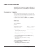
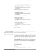
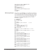
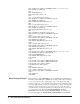
Table Of Contents
- Contents
- Warranty
- U.S. Government Restricted Rights
- WARNINGS
- Declaration of Conformity
- Chapter 1 Installing and Configuring the HP E1459A...
- Functional Description
- Configuring for Installation
- WARNING SHOCK HAZARD. Only qualified, service-trai...
- WARNING SHOCK HAZARD. When handling user wiring co...
- WARNING SHOCK HAZARD. Use wire with an insulation ...
- Caution MAXIMUM VOLTAGE. Maximum allowable voltage...
- Caution STATIC-SENSITIVE DEVICE. Use anti-static p...
- Setting the Logical Address
- Setting the Interrupt Priority
- Note Consult your mainframe manual to be sure that...
- WARNING To prevent electric shock, tighten facepla...
- WARNING To prevent the spread of fire in the case ...
- Chapter 2 Using the HP E1459A Module
- Chapter 3 HP E1459A SCPI Command Reference
- Common Command Format
- SCPI Command Format
- DIAGnostic:SYSReset Subsystem
- DISPlay:MONitor Subsystem
- INPut Subsystem
- MEASure Subsystem
- MEMory Subsystem
- SENSe Subsystem
- DAV
- NEDGe
- PEDGe
- Syntax
- [SENSe:]EVENt:PORTn:DAVailable?
- [SENSe:]EVENt:PORTn:DAVailable:ENABle
- [SENSe:]EVENt:PORTn:DAVailable:ENABle?
- [SENSe:]EVENt:PORTn:EDGE?
- [SENSe:]EVENt:PORTn:EDGE:ENABle
- [SENSe:]EVENt:PORTn:EDGE:ENABle?
- [SENSe:]EVENt:PORTn:NEDGe?
- [SENSe:]EVENt:PORTn:NEDGe:ENABle
- [SENSe:]EVENt:PORTn:NEDGe:ENABle?
- [SENSe:]EVENt:PORTn:PEDGe?
- [SENSe:]EVENt:PORTn:PEDGe:ENABle
- [SENSe:]EVENt:PORTn:PEDGe:ENABle?
- [SENSe:]EVENt:PSUMmary:DAVailable?
- [SENSe:]EVENt:PSUMmary:EDGE?
- STATus Subsystem
- Note Transition filters are always set for positiv...
- Note The Questionable Status Condition, Event, and...
- STATus:OPERation:CONDition?
- STATus:OPERation:ENABle
- STATus:OPERation:ENABle?
- STATus:OPERation[:EVENt]?
- STATus:OPERation:PSUMmary:CONDition?
- STATus:OPERation:PSUMmary:ENABle
- STATus:OPERation:PSUMmary:ENABle?
- STATus:OPERation:PSUMmary[:EVENt]?
- STATus:PRESet
- STATus:QUEStionable:CONDition?
- STATus:QUEStionable:ENABle
- STATus:QUEStionable:ENABle?
- STATus:QUEStionable[:EVENt]?
- SYSTem Subsystem
- IEEE 488.2 Common Commands
- Command Quick Reference
- Appendix A HP E1459A Specifications
- Max Input Voltage: Between High and Low terminal o...
- Module Size/Device Type: C, Register-based.
- Connectors Used: P1 and P2.
- Number of Slots: 1
- VXIbus Interface Capability: Interrupter, D16.
- Interrupt Level: 1-7, selectable.
- Power Requirements: Voltage: +5Vdc Peak Module Cur...
- Watts/Slot: 1.0
- Minimum Pulse Width: 100ms + debounce time.
- Operating Range:
- Debounce: Programmable from 16 mS to 1074 S.
- 5 Volt Supply: Output voltage : 4.5 to 5.5 V DC. M...
- Typical Time to Read 16-bit Word: 4 mS using regis...
- Terminal Module: Screw type, removable, maximum wi...
- Appendix B HP E1459A Register Definitions
- Overview
- Addressing the Registers
- The following commands are sent to the HP E1406 Co...
- When using an embedded controller VXI A16 address ...
- For example, for the HP 75000 Series C Mainframe w...
- base address (h) = (logical addressh)*40h + C000h
- For the HP E1459A, the factory-set logical address...
- base address = (90h)*(40h) + C000h> = E400h
- register address = [A16 location]h + [base addr]h ...
- The following registers can be accessed on the HP ...
- ID register (base = 00h) is a read only register. ...
- * Returns FFFFh = Hewlett-Packard A16 (only) regis...
- Device Type register (base = 02h) is a read only r...
- NOTE: Bits 8 and 9 are returned in the IACK respon...
- WRITE R = Reset to power-on state by writing a "1"...
- READ E IRQ = When "1" it indicates that an INTRX l...
- INTRX = Edge interrupt for port 0 - 3. A "1" means...
- DAVX = Data available in Port 0 - 3. A "1" means t...
- DOGENAB = "0" the watchdog timer is disabled. "1" ...
- DOGSTATE = "0" the watchdog timer is not asserted....
- For reading and writing, when BS = 0 in the Status...
- EDGE ENAB = "1" allows an edge interrupt (INTR for...
- INT/EXT = "0" data will be latched using the inter...
- DAV ENAB = "1" allows the DAV0/2 line to cause an ...
- Channels 0 through 15 are accessed when BS = 0 in ...
- Channels 32 through 47 are accessed when BS = 1 in...
- For Positive/Negative Edge Detect and Mask Registe...
- For Positive/Negative Edge Detect and Mask Registe...
- When BS = 0 in the Status/Control Register, the de...
- When BS = 1 in the Status/Control Register, the de...
- The following table lists the actual values for th...
- Register Value
- Bit pattern (hex)
- Clock Frequency
- Clock Period
- Debounce Time (4 - 4.5 clock periods)
- 2 (or 0, default)
- 0002h
- 250 kHz
- 4 mS
- 16 - 18 mS
- 3 (or 1)
- 0003h
- 125 kHz
- 8 mS
- 32 - 36 mS
- 4
- 0004h
- 62.5 kHz
- 16 mS
- 64 - 72 mS
- 5
- 0005h
- 31.25 kHz
- 32 mS
- 128 - 144 mS
- 6
- 0006h
- 15.63 kHz
- 64 mS
- 256 - 288 mS
- 7
- 0007h
- 7.81 kHz
- 128 mS
- 512 - 576 mS
- 8
- 0008h
- 3.90 kHz
- 256 mS
- 1.0 - 1.13 mS
- 9
- 0009h
- 1.95 kHz
- 512 mS
- 2.0 - 2.26 mS
- 10
- 000Ah
- 976 Hz
- 1 mS
- 4.1 - 4.6 mS
- 11
- 000Bh
- 488 Hz
- 2 mS
- 8.2 - 9.2 mS
- 12
- 000Ch
- 244 Hz
- 4.1 mS
- 16.4 - 18.4 mS
- 13
- 000Dh
- 122 Hz
- 8.2 mS
- 32.8 - 36.9 mS
- 14
- 000Eh
- 61 Hz
- 16.4 mS
- 65.5 - 73.8 mS
- 15
- 000Fh
- 30.5 Hz
- 32.8 mS
- 131 - 148 mS
- 16
- 0010h
- 15.3 Hz
- 65.5 mS
- 262 - 294 mS
- 17
- 0011h
- 7.63 Hz
- 131 mS
- 524 - 59 mS
- 18
- 0012h
- 3.82 Hz
- 262 mS
- 1.05 - 1.16 S
- 19
- 0013h
- 1.91 Hz
- 524 mS
- 2.1 - 2.36 S
- 20
- 0014h
- 0.954 Hz
- 1.05 S
- 4.2 - 4.72 S
- 21
- 0015h
- 0.477 Hz
- 2.1 S
- 8.39 - 9.43 S
- 22
- 0016h
- 0.238 Hz
- 4.2 S
- 16.8 - 18.9 S
- 23
- 0017h
- 0.119 Hz
- 8.39 S
- 33.6 - 37.8 S
- 24
- 0018h
- 60.0 mHz
- 16.8 S
- 67.1 - 75 S
- 25
- 0019h
- 30.0 mHz
- 33.6 S
- 134 - 150 S
- 26
- 001Ah
- 15.0 mHz
- 67.1 S
- 268 - 300 S
- 27
- 001Bh
- 7.5 mHz
- 134 S
- 537 - 600 S
- 28
- 001Ch
- 3.7 mHz
- 268 S
- 1074 - 1200 S
- 29
- 001Dh
- 1.9 mHz
- 537 S
- 2147 - 2400 S
- 30
- 001Eh
- 931 mHz
- 1074 S
- 4295 - 4800 S
- 31
- 001Fh
- 465.5 mHz
- 2148 S
- 8590 - 9600 S
- Command Register Port 1/3
- Command Register Port 1/3 (base + 20h)
- For reading and writing, when BS = 0 in the Status...
- EDGE ENAB = "1" allows an edge interrupt (INTR for...
- INT/EXT = "0" data will be latched using the inter...
- DAV ENAB = "1" allows the DAV1/3 line to cause an ...
- Channels 16 through 31 are accessed when BS = 0 in...
- For Positive/Negative Edge Detect and Mask Registe...
- For Positive/Negative Edge Detect and Mask Registe...
- When BS = 0 in the Status/Control Register, the de...
- Register Value
- Bit Pattern (Hex)
- Clock Frequency
- Clock Period
- Debounce Time (4 - 4.5 Clock Periods)
- 2 (or 0 ) Default
- 0002h
- 250 kHz
- 4 mS
- 16 - 18 mS
- 3 (or 1)
- 0003h
- 125 kHz
- 8 mS
- 32 - 36 mS
- 4
- 0004h
- 62.5 kHz
- 16 mS
- 64 - 72 mS
- 5
- 0005h
- 31.25 kHz
- 32 mS
- 128 - 144 mS
- 6
- 0006h
- 15.63 kHz
- 64 mS
- 256 - 288 mS
- 7
- 0007h
- 7.81 kHz
- 128 mS
- 512 - 576 mS
- 8
- 0008h
- 3.90 kHz
- 256 mS
- 1.0 - 1.13 mS
- 9
- 0009h
- 1.95 kHz
- 512 mS
- 2.0 - 2.26 mS
- 10
- 000Ah
- 976 Hz
- 1 mS
- 4.1 - 4.6 mS
- 11
- 000Bh
- 488 Hz
- 2 mS
- 8.2 - 9.2 mS
- 12
- 000Ch
- 244 Hz
- 4.1 mS
- 16.4 - 18.4 mS
- 13
- 000Dh
- 122 Hz
- 8.2 mS
- 32.8 - 36.9 mS
- 14
- 000Eh
- 61 Hz
- 16.4 mS
- 65.5 - 73.8 mS
- 15
- 000Fh
- 30.5 Hz
- 32.8 mS
- 131 - 148 mS
- 16
- 0010h
- 15.3 Hz
- 65.5 mS
- 262 - 294 mS
- 17
- 0011h
- 7.63 Hz
- 131 mS
- 524 - 590 mS
- 18
- 0012h
- 3.82 Hz
- 262 mS
- 1.05 - 1.18 S
- 19
- 0013h
- 1.91 Hz
- 524 mS
- 2.1 - 2.36 S
- 20
- 0014h
- 0.954 Hz
- 1.05 S
- 4.2 - 4.72 S
- 21
- 0015h
- 0.477 Hz
- 2.1 S
- 8.39 - 9.43 S
- 22
- 0016h
- 0.238 Hz
- 4.2 S
- 16.8 - 18.9 S
- 23
- 0017h
- 0.119 Hz
- 8.39 S
- 33.6 - 37.8 S
- 24
- 0018h
- 60 mHz
- 16.8 S
- 67.1 - 75 S
- 25
- 0019h
- 30 mHz
- 33.6 S
- 134 - 150 S
- 26
- 001Ah
- 15 mHz
- 67.1 S
- 268 - 300 S
- 27
- 001Bh
- 7.5 mHz
- 134 S
- 537 - 600 S
- 28
- 001Ch
- 3.7 mHz
- 268 S
- 1074 - 1200 S
- 29
- 001Dh
- 1.9 mHz
- 537 S
- 2147 - 2400 S
- 30
- 001Eh
- 931 mHz
- 1074 S
- 4295 - 4800 S
- 31
- 001Fh
- 466 mHz
- 2147 s
- 8590 - 9600 s
- Power On/Reset Conditions
- Programming Examples
- Appendix C Error Messages
- Index

98 HP E1459A Register Definitions
860 OUTPUT Vxi_address;"VXI:READ? 128,8"
! get dav status register
870 ENTER Vxi_address;A
880 !
890 A=BINAND(A,15)
900 PRINT "DAV Status: ";A
910 !
915 ! get dav data register, port 0
920 OUTPUT Vxi_address;"VXI:READ? 128,18"
930 ENTER Vxi_address;A
940 PRINT "DAV Data Reg Port 0: ";A
950 !
955 ! get dav data register, port 1
960 OUTPUT Vxi_address;"VXI:READ? 128,34"
970 ENTER Vxi_address;A
980 PRINT "DAV Data Reg Port 1: ";A
990 !
995 ! E1459A ints disabled, port 2/3 select
1000 OUTPUT Vxi_address;"VXI:WRITE 128,4,16"
1010 !
1015 ! get dav data register, port 2
1020 OUTPUT Vxi_address;"VXI:READ? 128,18"
1030 ENTER Vxi_address;A
1040 PRINT "DAV Data Reg Port 2: ";A
1050 !
1055 ! get dav data register, port 3
1060 OUTPUT Vxi_address;"VXI:READ? 128,34"
1070 ENTER Vxi_address;A
1080 PRINT "DAV Data Reg Port 3: ";A
1090 !
1100 OUTPUT Vxi_address;"VXI:READ? 128,8"
! get dav status register
1110 ENTER Vxi_address USING "#,K";E
1120 Istat=BINAND(E,15)
1130 PRINT "DAV Status Reg: ";Istat
1140 PRINT
1150 !
1160 OUTPUT Vxi_address;"DIAG:INT:SET1 ON"
1170 OUTPUT Vxi_address;"DIAG:INT:ACT ON"
1180 OUTPUT Vxi_address;"*OPC?"
1190 ENTER Vxi_address;Done
1200 !
1210 ENABLE INTR 7;2
1215 ! dav int enabled, port 0/1 select
1220 OUTPUT Vxi_address;"VXI:WRITE 128,4,64"
1230 !
1240 RETURN
1250 END
Mixed Interupt Example This example is coded in HP RMB for a System 9000 (Series 300) linked to
a E1406 Command Module via HPIB. The example enables all four channel
ports to detect both positive and negative edges on the high order eight
channels of any port. (Any unmasked edge will generate an interrupt.) The
low order eight channels of each port are defined for capture of an eight bit
data byte. (An interrupt will also be generated on the occurrence of an
external capture clock at any channel port.) When idle, the program will
loop and continuously display the EDGE INTERRUPT STATUS
REGISTER and the DATA AVAILABLE REGISTER. On interrupt, the
program will display the EDGE DETECT REGISTERS and CHANNEL