HP E5000 Messaging System for Microsoft Exchange Administrator Guide Abstract This document explains how to install, configure, and maintain all models of the E5000 Messaging System for Micosoft Exchange. The intended audience is decision makers, IT support staff, and project managers involved in planning and deploying Microsoft Exchange Server 2010 solutions. For more information on Exchange 2010 terminology and best practices, go to http://www.hp.com/solutions/activeanswers/exchange.
© Copyright 2011 Hewlett-Packard Development Company, L.P. Confidential computer software. Valid license from HP required for possession, use or copying. Consistent with FAR 12.211 and 12.212, Commercial Computer Software, Computer Software Documentation, and Technical Data for Commercial Items are licensed to the U.S. Government under vendor's standard commercial license. The information contained herein is subject to change without notice.
Contents 1 HP E5000 Messaging Systems for Microsoft Exchange....................................7 2 Preparing to install the messaging system.......................................................9 Exchange Server 2010 network requirements................................................................................9 E5000 EMU network connections...............................................................................................9 Planning the E5300 Messaging System network configuration........
6 Updating system software and firmware......................................................63 Powering off the messaging system............................................................................................63 Determining the current messaging system software version..........................................................63 Updating the messaging system software...................................................................................63 Upgrading a component's firmware version......
Restoration in production environments................................................................................149 9 Support and other resources....................................................................150 Contacting HP......................................................................................................................150 HP technical support........................................................................................................150 Subscription service.....
Taiwanese notices.................................................................................................................191 BSMI Class A notice.........................................................................................................191 Taiwan battery recycle statement........................................................................................191 Vietnamese notice............................................................................................................
1 HP E5000 Messaging Systems for Microsoft Exchange The HP E5000 Messaging System for Microsoft Exchange (“messaging system”) is an integrated hardware-software solution that simplifies the initial deployment of Microsoft Exchange Server 2010. Each messaging system features HP server blades and dense disk storage in a single 3U enclosure (Figure 1 (page 7)). E5000 expansion nodes are optional or standard depending on the model.
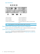
Figure 2 HP E5000 Messaging System rear view 1. System fan 2. HP StorageWorks 2-port Ethernet I/O module (2) (These modules connect to the NIC located on the server blade motherboard) 3. Drive fan 4. SAS I/O module (2) 5. Power button 6. Power supply (2) 7. HP StorageWorks 2-port Ethernet I/O module (These modules (2) connect to the NIC located on top of the Mezzanine card on the server blade. Standard on the E5500 and E5700 and can be added as option for the E5300 8.
2 Preparing to install the messaging system Before you install the messaging system, plan how you will integrate the system into your network and whether you will use Insight Remote Support (see “HP Insight Remote Support software” (page 60)).
Figure 3 Network ports 1. Server 1, NIC, port 1 6. Server 2, Mezz NIC, port 2 2. Server 2, NIC port 1 7. Server 1, Mezz NIC, port 2 3. Server 1, NIC port 2 8. Server 2, Mezz NIC, port 1 4. Server 2, NIC port 2 9. Server 1, Mezz NIC, port 1 5. E5000 enclosure power button 10. Enclosure Manager NIC. Includes ilO connections for both servers. NOTE: E5300 models do not come standard with Mezz NICs on the servers.
Figure 4 Recommended E5300 Messaging System network configuration 1. Clients 4. Domain controller 2. Client/MAPI network 5. Replication network 3. File share witness 6. Firewall By default, the E5000 Configuration Wizard sets up the Client/MAPI and Replication networks as follows: • • Client/MAPI network ◦ Server 1/Port 1 and Server 2/Port 2 network ports connect to this network. ◦ Labels this network as the MAPI network on each server.
Figure 5 E5300 Messaging System connection options 1. Client/MAPI network 2. Replication network 3. Connection to EMU Planning the E5500/E5700 Messaging System network configuration This section describes the typical E5500/E5700 network configuration and EMU connection options.
• ◦ Server1/Port 1 and Server2/Port 2 network ports connect to this network. ◦ The network is labeled as the MAPI network on each server. Replication network ◦ Server 1-Mezz NIC/Port 1 and Server 2-Mezz NIC/Port 1 network ports connect to this network. ◦ The E5000 Configuration Wizard automatically assigns these static addresses: – Server 1 – 10.0.0.1 – Server 2 – 10.0.0.
3 Installing the messaging system This chapter explains how to install the messaging system hardware. Check the kit contents Remove the contents, making sure you have all the components listed below. If components are missing, contact HP technical support. Hardware • HP E5000 Messaging System base system configuration • Expansion nodes if deploying an E5700 configuration or if purchased as an upgrade option for other configurations • Power cords • 1.2m CAT5 Ethernet cable • 0.
Unpack and rack the messaging system hardware WARNING! The messaging system enclosure is heavy. Always use at least two people to move the storage system into the rack. 1. If you ordered the messaging system without the rack, install the rail kit and enclosure by following the HP Rail Kit Installation Instructions that are included with the rail kit. If your messaging system is delivered in a rack, proceed to Step 2.
2. If you purchased an expansion node, rack and cable the expansion node(s) before moving to the next step. a. Add expansion nodes to the rack by following the HP StorageWorks 2U Storage System Rail Kit Installation Instructions, packaged with the rail kit. b. Cable the expansion nodes to the messaging system chassis. For recommended cabling, see “Install E5000 expansion nodes” (page 16). 3. Cable the messaging system to your network and attach the power cords.
Figure 8 (page 17) shows an E5700 maximum configuration with 4 expansion nodes. Figure 8 E5700 maximum configuration with 4 expansion nodes 1. Messaging System 2–5. Expansion nodes 6. SAS cable connecting expansion node 1 (green cable) 7. Green color code for upper SAS I/O module 8. Red color code for lower SAS I/O module 9. SAS cable connecting expansion node 2 (red cable) Power on the messaging system 1. 2. Power on any expansion nodes.
Configure the EMU and iLO management processors as follows on both servers. 1. Establish physical connectivity to the EMU port. 1. Connect the EMU NIC port directly to a local system or laptop. You can use either a crossover or a straight through Ethernet cable. 2. Configure the TCP/IP properties: 1. Open Control Panel. 2. 3. • For computers running Windows Visa or Windows 7, select Network and Sharing Center. • For computers running Windows XP, select Network Connections.
logged into the iLO, you can change the Administrator password and select the Administration tab under the User Administration section. 3. 3. Under the Administration tab, configure the network as required for your environment. Select the section labeled Network. You can either enable DHCP or edit the IP address details and enter site-specific network settings. The following example shows a DHCP configuration. 4. 5. After completing your changes, click Apply to save your settings.
1. Connect to the Enclosure Manager software using an ssh compatible tool like PuTTY. In the PuTTY session basic options, enter the IP address of the EMU (10.0.0.10), port 22, and connection type SSH. TIP: The password is printed on a tear away label attached to the top rear of the enclosure.
2. After you have connected to the EMU, set the following attributes: • EMU (DNS) name • rack name • EMU password • IP addressing method. Example 1 Setting attributes E5000-1-EM> set em name E5000-1-EM IDP Enclosure Manager name changed to E5000-1-EM. E5000-1-EM> set rack name CustomerRackName Changed rack name to "CustomerRackName". E5000-1-EM> set password New Password: ******** Confirm : ******** Changed password for the "Administrator" user account.
http://www.hp.com/go/ilo. On the iLO web page, select iLO Firmware (under iLO Support & Downloads, on the right), then select Manuals (from menu on the left). If you are using the direct connect method, connect the supplied SUV cable to the front of the messaging system server blades in the following sequence: keyboard, mouse, monitor cable, and monitor power cable. NOTE: The keyboard, mouse, and monitor are not provided with the messaging system. Figure 9 Keyboard, mouse, and monitor 1.
7. 8. Rebalance the databases using the RedistributeActiveDatabases.ps1 script located (by default) at \Program Files\Microsoft\Exchange Server\V14\scripts. Run this script within the Exchange Management Console. Within the Microsoft Exchange Management Console, select New Mailbox Database. a. Name the new database the next item in the sequence (for example, DB10). b. Select a server. c. Set the path based on the newly created LUNs. 9. Use Microsoft Exchange Management Console to add a mailbox copy.
4 Configuring the messaging system software This chapter explains how to configure system software using the HP E5000 Configuration Wizard and how to deploy Microsoft Exchange Server 2010 using the HP E5000 Messaging System Exchange Deployment Tool. IMPORTANT: blade.
Click Next. 4. Set the time zone and then click Next. The correct local time zone is set when the server joins a domain.
5. 26 Set the Administrator password and then click Next.
6. Set the network configuration. Review each network port configurations and either accept the default values or press Edit to change them. Click Next when finished. IMPORTANT: By default, the Replication network is set to a static network 10.0.0.0/30 with IP 10.0.0.1 on the first node and 10.0.0.2 on the second. If these addresses conflict with addresses on your network, please reconfigure them to some other unused static network.
7. Set the computer name and join a domain. Enter the computer name and the name of the domain that the computer will join. Enter the name and password of a user who has permission to add the computer to the domain. Click Next when finished. IMPORTANT: Be sure to record the name of the first server. You need that name when you configure the second server.
8. Review the summary report and complete the configuration. The Summary screen lists the configuration settings you have made. 9. Click Configure to apply the configuration settings or Back to modify them. When you are ready to accept the settings, click Finish to reboot the server. If you do not want to reboot at this time, clear the box Reboot after exiting the wizard. NOTE: The server blades contain redundant storage controllers. When a server reboots, one of the controllers shuts down.
Deploying Microsoft Exchange Server 2010 Follow this procedure to deploy Microsoft Exchange Server 2010. Complete the deployment of Microsoft Exchange Server 2010 on the bay 1 server blade before beginning the configuration of the bay 2 server blade. IMPORTANT: Before proceeding, ensure that Active Directory has been prepared in accordance with http://go.microsoft.com/?linkid=9738614. You must also provide a witness server to be used by the DAG.
a. A normal run of the Jetstress test provides a baseline benchmark of the system. HP recommends that you run the test now, but only if you have sufficient time before deploying the server into production. Click Next to begin deployment of the Exchange Administration Tools. This should take approximately five minutes. NOTE: b. A normal run of the Jetstress test can take 24 hours to complete.
NOTE: When you reach this screen while deploying to the bay 1 server, select First blade. The Exchange Deployment Tool automatically detects whether any are found in the existing Exchange organization (when existing is selected). When you reach this screen while deploying to the bay 2 server, select Second blade, and then enter the name of the bay 1 server (not the name of the bay 2 server). Complete each item on this screen as needed for your deployment: • New or existing Availability Group (DAG) name.
• • Enter the name of your load-balanced CAS array which is set on the database property. If no load-balanced CAS array is available, see: ◦ http://go.microsoft.com/?linkid=9738617 ◦ http://go.microsoft.com/?linkid=9738618 Enable Error Reporting. For more information, see http://go.microsoft.com/?linkid=9738619 nl • Create Public Folder database. To connect to Exchange 2010 Microsoft Entourage or Outlook 2003, clients require a public folder database.
When the process completes, you are prompted to allow the server to reboot. After the reboot, log in again with Exchange administrator credentials (see http://technet.microsoft.com/en-us/ library/ee681663.aspx) to complete the deployment (the Exchange Deployment Tool reappears automatically when you log in). 6. After deployment completes, the Exchange Deployment Tool displays a success message and prompts you to run the Best Practices Analyzer.
The Exchange Best Practices Analyzer is located in the Toolbox node in the Exchange Management Console. You can use the Best Practices Analyzer to connect to Directory, start a scan, and perform other Exchange operations. For more information about Microsoft Exchange Server 2010 and to download the complete help file, see Exchange Server 2010 at http://technet.microsoft.com/en-us/library/bb124558.aspx.
IMPORTANT: You must run these tools in a non-production environment to avoid potential loss of data and performance degradation. For more information about these tools, see Tools for Performance and Scalability Evaluation at http://technet.microsoft.com/en-us/library/dd335108.aspx. If you are testing Jetstress, only the E5000 servers are required. The servers must not have Exchange loaded when running Jetstress.
5 Monitoring and troubleshooting the messaging system The messaging system provides several monitoring and troubleshooting options.
Table 1 Examples of possible error messages (continued) Message appears Issue Resolution You are prompted to enter the Administrator password during the initial configuration by the Configuration Wizard. The messaging system attempts to locate the domain and then report the problem when it is unable to locate the domain you entered.
Table 1 Examples of possible error messages (continued) Message appears Issue Resolution Lost replication connection Replication and MAPI network not connected Connect the cable in the back of the enclosure. If the cable is not on, you must use a MAPI network. For the E5300, which does not offer replication networking, you may use a public network for replication and need to configure the IP address manually.
1. 40 Click Start→All Programs→HP Management Agents→Event Notifier Config. a. On the Welcome window, click Next. b. Enter your address and mail server information to set up the Mail (SMTP) Server Information, and then click Next. c. On the Event Recipients Information screen, click Add to add a notification recipient.
d. Add a user name and address to the Notification Recipient Information dialog box, and then click OK. Repeat this step for each user. Click Finish after completing the notification list.
e. 2. 42 Select the events for which you want to be notified, and then click OK. HP recommends that you select all events. To configure the SNMP settings, provide the contact and location information for the System Administrator, and then click OK.
3. To make SNMP visible externally: 1. Select Start→Administrative Tools→Services. 2. Select SNMP Service. 3. Right click and select Properties to display the SNMP Service properties. 4. Select the Security tab and specify the following items: • The external hosts that may use the SNMP protocol. • The SNMP Community string. HP recommends that you use something other than the typical ‘Public’ string. IMPORTANT: Configure HP SIM security to prevent the SIM management server from gaining access to SNMP.
Table 2 System status tray description Icon check mark color Description Green The system is running a supported configuration. Red The system is running an unsupported configuration. The system tray icon shows a red error symbol until Microsoft Exchange has been fully installed, or if the system is running outside the terms of the service and support agreement (for example, the system is running a server application other than Microsoft Exchange).
Exchange Status The Exchange Status tab in the System Manager provides the overall Microsoft Exchange configuration status (by default). Click any configuration item in the list at the top to see further refined detail.
Firmware The Firmware tab indicates whether the firmware of a component is outdated. To review the components firmware version status, open the System Manager and click the Firmware tab. If the specific firmware requires that you reboot after installing the update, a message instructing you to reboot the messaging system appears. Since the tool does not connect to the Internet to identify new firmware, you must periodically check the HP support web page and download new firmware when available.
IMPORTANT: If a firmware update requires a reboot, you must reboot your messaging system manually. For more information about firmware updates, see“Upgrading a component's firmware version” (page 64) . Reports The Reports tab gathers logs for the hardware, software, Microsoft Windows system configuration, and the Microsoft Exchange diagnostics in one place. These logs are used by HP support engineers to help diagnose your system, if needed; you do not need to view and interpret the logs yourself.
HP System Management Homepage The HP System Management Homepage (HP SMH) is a web-based interface that consolidates and simplifies single system management for HP servers. The SMH is the primary tool for identifying and troubleshooting hardware issues in the messaging system. You may choose this option to drill down to a suspected hardware problem.
Starting the System Management Homepage application To start the application, double-click the HP System Management Homepage desktop shortcut or enter https://hostname:2381/ in Internet Explorer. The hostname can be localhost or the IP address of the server you want to monitor. To log into SMH, enter the same username and password you use to log in to the server. Users who have administrative privileges on the server have the same privileges in the SMH application.
NOTE: When you remove a disk or disconnect a cable, the System Management Homepage GUI might not display alerts when you click the Refresh button. You can force a hard refresh by clicking the Home button or by drilling down to the problem area. The default refresh interval is 2 minutes. To change the interval in the Settings menu, select Autorefresh, and then Configure Page refresh settings. The minimum interval is 5 seconds and the maximum is 30 minutes.
• Storage Pools A list of storage pools associated with the controller displays in the left panel tree view. Select one of the pool entries to display its status, capacity, communication status with the controller, primordial state, and cache properties. NOTE: If read or write cache is enabled the value displayed is 2; otherwise, the value is 3. The Storage Pools page also displays a list of disk drives and storage volumes present in the pool.
Figure 11 Server blade(s) LEDs Table 3 Server blade LEDs status Item Description Status 1 UID LED Blue = Needs service check Blue flashing = remote management (remote console in use via iLO) Off = No remote management 2 Health LED Green = Normal Flashing = Booting Amber = Degraded condition Red = Critical condition 3 NIC 1 LED* Green = Network linked Green flashing = Network activity Off = No link or activity 4 Flex-10 NIC 2 LED* Green = Network linked Green flashing = Network activity Off =
Figure 12 Front LED display board Table 4 Front LED status descriptions Item Description Status 1 Hard drive LEDs Green = The drive is online, but is not currently active. Normal mode (UID LED is solid) Flashing irregularly green = The drive is and it is operating normally. Flashing green (1 Hz) = Do not remove the drive. Removing the drive may terminate the current operation and cause data loss.
NOTE: All these LEDs are off if the enclosure has power but is turned off (see Table 11 (page 57)). Then only the equivalent Chassis LEDs (2,3,4) on the rear Power Pod shows status. Figure 13 Hard drive LEDs 1. Fault/UID LED (amber/blue) 2. Online LED (green) Table 5 SAS hard drive LED combinations Item Description Status 1 Activity/0nline LED Green = Force Off (override drive activity output).
Figure 14 Cache module controller LEDs Table 6 Cache module ontroller LED status description Item Description Status Green LED upper left; Controller LEDs Amber LED lower right Green off, amber on = A backup is in progress. Green flashing (1 Hz), amber on = A restore is in progress. Green flashing (1 Hz), amber off = The capacitor pack is charging.
Table 7 (continued) Item Description Status 3 EM health LED The health LED is only green and is either on (Healthy) or off (Power off or Faulted). LEDs are off when the enclosure is powered off.
Table 9 HP StorageWorks 2-port 1 Gb Ethernet, Mezz A and B I/O modules LEDs status description (continued) Item Description Status Off* when module health is good *LEDs are off when enclosure is powered off.
Table 11 Chassis switches and indicator LED status description (continued) Item Description Status 4 Power button/LED Green when enclosure power is ON. Amber when enclosure has AC power but is turned off.
The two fan modules are physically identical, but their control is not. The Fault/health LED on FAN 1 is a single bi-color LED controlled by the EMU via the Health Monitor – it is either off, steady green, or flashing amber. The lens of the fan LED is colorless and looks grayish-white when off. System Fan — Fan 1 Fan 1 LED is driven by the Health Monitor PSoC under direction of the EMP firmware. The fan microprocessor inside the Fan module cannot sense or control this LED.
Type 'HELP' to display a list of valid commands. Type 'HELP ' to display detailed information about a specific command. Type 'HELP HELP' to display more detailed information about the help system. EM 78E7D1020504> After logging in, you can set the Administrator password by running the HP-provided tool, C:\Program Files\HP\HP Configuration Wizard\HPEMConfig.exe. nl HP Support websites Use the “Support and troubleshooting” task at the HP Support & Drivers website (http://www.hp.
pronotification, but do not need proservice delivery and integration with a management platform. • HP Insight Remote Support Advanced: This software provides comprehensive remote monitoring and proservice support for nearly all HP servers, storage, network and SAN environments, plus selected non-HP servers than have a support obligation with HP. It is integrated with HP Systems Insight Manager. A dedicated server is recommended to host both HP Systems Insight Manager and HP Insight Remote Support Advanced.
Locating the messaging system warranty entitlement labels You must locate and identify the serial number and part number for the messaging system components to obtain service under the warranty. The numbers are listed on the warranty entitlement label located on the pull-out tab that is positioned below the Enclosure Management module, in the lower left-hand corner of the back of the enclosure.
6 Updating system software and firmware This section explains how to update system software and firmware. Powering off the messaging system Follow these steps whenever you need to shut down a single server blade or to perform a system shutdown of the messaging system: 1. 2. 3. 4. 5. 6. Go to the standard Windows path of Start > Shut Down. Shut down blade 2. Shut down blade 1.
11. Press OK to exit. 12. After Server 1 has completed the update, copy the file HPE5000Update_x_y_z.exe to Server 2 and repeat the update procedure. Upgrading a component's firmware version To determine whether a component requires a firmware upgrade, select the E5000 System Manager in Microsoft Server Manager. Click the System Summary tab, and inspect the Firmware update recommended icon status. If the icon is green , no firmware update is needed. If the icon is yellow , a firmware update is required.
IMPORTANT: You must check for firmware version upgrades on each server blade. Certain upgrades may only be performed on Server Blade 1, Bay 1, and other component firmware version upgrades may appear only on Server Blade 2, Bay 2. IMPORTANT: Firmware upgrades may impact information availability on the server blades during the upgrade. For instance, you cannot access information on the drives while they are updating. You need to gracefully shut down the messaging system for availability during the upgrade.
3. In the Components Available for Upgrades window, select the box next to each component to be upgraded. The Component Details box displays the firmware version that is currently running, and the available firmware version. NOTE: HP recommends that you upgrade one component at a time to ensure each version updates successfully. Carefully shut down Server 2, Bay 2 before using Server 1, Bay 1 to update the drives in the drawer. 4. 66 After selecting the components for update, click Apply Updates.
WARNING! When updating both controllers at the same time, you must update the firmware to sync it with the pared-down controller. This step takes the volumes offline because both pared-down servers must reboot. When the volumes go down, an auto-clone operation occurs, which means the firmware of the running controller is flashed onto the booting controller. This ensures that both controllers are running the same firmware version. If you have iSCSI, be sure to disconnect before beginning a firmware update.
The System Manager automatically notifies you when a firmware upgrade is available for an component. If a replacement component is running an earlier firmware version, the System Manager alerts you on the System Summary and Firmware tabs. In this instance, you do not need to download a firmware upgrade. NOTE: The firmware upgrade has failed if a component remains in the Components Available for Updates list after the firmware upgrade and reboot.
7 Removing and replacing hardware components This chapter describes procedures for removing and replacing hardware components. Customer self repair HP customer self repair (CSR) programs allow you to repair your StorageWorks product. If a CSR part needs replacing, HP ships the part directly to you so that you can install it at your convenience. Some parts do not qualify for CSR. Your HP-authorized service provider determines whether a repair can be accomplished by CSR.
Replaceable parts This product contains replaceable parts. To identify the replaceable parts, see the individual component guides listed in Table 14 (page 73). Parts that are available for CSR are indicated as follows: • Mandatory CSR — You order the part directly from HP and repair the product yourself. On-site or return-to-depot repair is not provided under warranty. • Optional CSR — You can order the part directly from HP and repair the product yourself, or you can request that HP repair the product.
Figure 23 Exploded view of the messaging system Table 13 (page 72) lists the CSR replaceable parts for the messaging system.
Table 13 Messaging system replaceable parts Item Replaceable unit (RU) Part number CSR availability Replacement type (Cold, Warm, Hot) 1 Server interposer 631117-001 Optional Cold 2 Midplane board 631115-001 Non Cold (Not shown) .
Table 14 Related component documents Component Component name Guide Server blade E5460sb blades BL460c maintenance and service guide Disks in expansion nodes HP E5000 Messaging System 12 TB expansion ode and HP E5000 Messaging System 24 TB expansion node HP StorageWorks D2600/D2700 Disk Enclosure User Guide Hot, warm, and cold swap components Hot or warm swapping a component means removing and replacing it while the main power is still on.
Verifying proper operation After replacing a messaging system component, check the following to verify that the component is operating properly: • If applicable, verify that the green LED is lit continuously or blinking. If not, try reseating the component. • From the System Manager, navigate to the Hardware Status and System Summary tabs to confirm the component failure alert no longer appears. The status should be (Good).
1. 2. 3. 5. Press upward on the release button on the hard drive drawer (1). Pull the drawer handle down 90 degrees (2). Extend the hard drive drawer (3). Label the hard drives. IMPORTANT: Use the drive labels provided with the replacement server interposer board when removing the drives to ensure you replace the drives in the correct order. 6. Remove all hard drives.
12. Open the release handle (1), and pull up to remove the server interposer board (2). NOTE: You may need to use significant force to accomplish this task. Replacing the server interposer board To replace the server interposer board: 1. With the release handle open, align the server interposer board with the alignment pins (1), and then close the server interposer release mechanism (2). NOTE: pins. 2. 3.
3. 6. Extend the hard drive drawer (3). Replace all hard drives. IMPORTANT: Install the hard drives in the same slots from which you removed them or the system might fail. Use the drive labels to ensure you replace the drives in the correct order. 7. 8. Push the hard drive drawer back into the messaging system enclosure. Plug in all cables at the back of the messaging system enclosure, and ensure that all cables are returned to their original locations. 9.
3. 5. Extend the hard drive drawer (3). Label the hard drives. NOTE: Use the drive labels provided with the replacement midplane board when removing the drives to ensure you replace the drives in the correct order. 6. Remove all hard drives. IMPORTANT: Install the hard drives in the same slots from which you removed them or the system might fail. 7. 8. 9. Push the drive drawer back into the messaging system enclosure. Label each server blade, and then remove both server blades.
NOTE: Make a note of all module locations so they can be placed back into their original locations. 14. Open the release handle (1), and pull up to remove the server interposer board (2). NOTE: This step may require significant force to accomplish. 15. Pull the drawer handle down 90 degrees, and slide out the hard drive drawer. 16. Remove the plug bracket (2) from the coil power plug by removing the thumbscrew (1). 17. Unplug the coil power assembly from the midplane board.
18. Extend the server blades. 19. Remove the server blade airflow baffle from inside the enclosure. 20. Unplug the power cable from the server blade midplane (1), and then unplug the rear UID PCA from the midplane board (2).
21. Loosen the two thumbscrews holding midplane board in place (1), pull the capacitive locking pin out of the midplane board (2), and then lift the midplane board out of the enclosure (3). Replacing the midplane board To replace the midplane board: 1. 2. Pull the capacitive locking pin out while inserting the midplane board.
13. Place the enclosure into the rack, and then tighten the two retaining screws. WARNING! The messaging system enclosure is heavy, even after removing the hard drives. Always use at least two people to replace the messaging system in the rack. 14. Replace both server blades in their original bays. 15. Extend the hard drive drawer: 1. Press upward on the release button on the hard drive drawer (1). 2. Pull the drawer handle down 90 degrees (2). 3. Extend the hard drive drawer (3). 16.
Replacing the SAS cable To replace the SAS cable: 1. Connect the SAS cable between the messaging system SAS I/O module and the switch. 2. Verify that the replacement SAS cable is working properly by checking the associated LED status. 3. Confirm that the messaging system has resumed normal operations. Removing and replacing the SAS I/O module IMPORTANT: Be sure to unpack the replacement part before you remove the existing component.
1. Insert the replacement SAS I/O module (1), and then push up on the SAS I/O module lever (2) until it locks into place. NOTE: 2. You may need to use significant force to accomplish this task. Plug in all cables to the SAS I/O module. IMPORTANT: You must install the SAS I/O cables in the same slots from which they are removed or the system might fail. 3. 4. 5. Verify that the replacement SAS I/O module is working properly by checking the associated LED status. Confirm the firmware version.
Removing the drive fan module To remove the drive fan module: 1. 2. 3. Use System Manager to identify the failed component. Verify the failed component by checking for a blinking amber LED on the failed component. Press upward on the drive fan module release lever (1). 4. Remove the drive fan module (2). Replacing the drive fan module To replace the drive fan module: 1. Insert the replacement fan module. 2.
3. Confirm that the messaging system has resumed normal operations. NOTE: It should take approximately 15 seconds for the LED status to appear. Removing and replacing the server fan module CAUTION: You must replace the server fan module within 3 minutes or you might lose data. The total time allowance is 3 minutes for replacing the driver module, which includes the removal of the original server fan module and installation of the replacement fan.
2. 3. Verify that the replacement fan module is working properly by checking the associated LED status. Confirm that the messaging system has resumed normal operations. Removing and replacing the power UID button assembly This section describes how to remove and replace the power UID button assembly in the messaging system. Removing the power UID button assembly To remove the power UID button assembly: 1. Power off the system: 1.
NOTE: Use the drive labels provided with the replacement rear power UID button assembly when removing the drives to ensure you replace the drives in the correct order. 4. Remove all hard drives. IMPORTANT: Install the hard drives in the same slots from which you removed them or the system might fail. 5. 6. 7. 8. Push the drive drawer back into the messaging system enclosure. Label each blade and then remove both server blades.
11. Unplug the cable from the power UID button assembly (1) and remove the screw from the power UID button assembly (2). Then remove the faulty power UID button assembly (3). Replacing the power UID button assembly To replace the power UID button assembly: 1. Install the replacement power UID button assembly (1) and replace the screw in the power UID button assembly (2). Then plug the cable into the power UID button assembly (3). 2. 3. 4. 5.
3. 8. Extend the hard drive drawer (3). Replace all hard drives. IMPORTANT: Install the hard drives in the same slots from which you removed them or the system might fail. Use the drive labels to ensure they are replaced in the correct order. 9. 10. 11. 12. Push the drive drawer back into the messaging system enclosure. Plug in all cables at the back of the messaging system enclosure into their original locations. Power on the messaging system.
Removing the HP StorageWorks Ethernet I/O module To remove the HP StorgeWorks Ethernet I/O module in the network or Mezz slots of the system enclosure: 1. 2. 3. 4. Use System Manager to identify the failed component. Verify the failed component by checking for a blinking amber LED on the failed component. Label the cables, and then unplug all cables from the HP StorageWorks Ethernet I/O module. Press the module release mechanism to the right (1), and then remove the failed module (2).
5. Confirm that the messaging system has resumed normal operations. NOTE: It should take approximately 15 seconds for the LED status to display. Removing and replacing the Mezzanine NIC Removing the Mezzanine NIC Optional Mezzanine cards enable network connectivity or provide Fibre Channel support. The Mezzanine NIC might have captive screws that are required to secure it to the server blade. When installing a Mezzanine NIC in this server blade, only two captive screws are required.
8. Open the ejector latches (1) on each side of the cache module slot. Typically, opening the ejector latches ejects the cache module automatically. If the module does not eject automatically after you open the ejector latches, remove the cache module (2) by grasping only the edges. 9. Remove the cache module and the capacitor from the blade. 10. The Mezzanine NIC is underneath the controller card. Remove the controller card by loosening the captive screws (1), and then remove the Mezzanine NIC (2). 1.
• 8. If the amber LED is not lit, proceed to the next step. Open the ejector latches (1) on each side of the cache module slot. Typically, opening the ejector latches ejects the cache module automatically. If the module does not eject automatically after you open the ejector latches, remove the cache module (2) by grasping only the edges. 9. Remove the cache module and the capacitor from the blade. 10. The Mezzanine NIC is underneath the controller card.
4. Confirm the firmware version. NOTE: You must reboot the storage solution after updating Mezzanine NIC and server blade firmware. Removing and replacing the PCIe module (with card) IMPORTANT: Be sure to unpack the replacement part before you remove the existing component. This section describes how to remove and replace the PCIe module (with card) in the messaging system. Removing the PCIe module To remove the PCIe module: 1. 2. 3. Use System Manager to identify the failed component.
7. Remove the two screws from the bracket of the failed PCIe module (1), remove the bracket (2), and then remove the PCIe card from the failed module (3). Replacing the PCIe module To replace the PCIe module: 1. Install the PCIe card in the replacement module (1), replace the bracket (2), and then reinsert the two screws into the bracket of the replacement module (3). 2. Insert the replacement PCIe module into the system (1), and lock the release lever (2). NOTE: 3. 4.
5. 6. Verify that the replacement component is working properly by checking the associated LED status. Confirm the system has resumed normal operations. Removing and replacing the Enclosure Manager Unit IMPORTANT: Be sure to unpack the replacement part before you remove the existing component. This section describes how to remove and replace the Enclosure Manager Unit in the messaging system. Removing the Enclosure Manager Unit module To remove the Enclosure Manager Unit module: 1. 2. 3. 4.
2. 3. 4. 5. Plug the cables back into the Enclosure Manager Unit module. Verify that the new component is working properly by checking the associated LED status. Confirm the firmware version. Obtain an IP address. IMPORTANT: Some of the configuration information is automatically repopulated, but you must reconfigure the network settings and password. 6. Confirm the system has resumed normal operations. NOTE: This may take approximately 1 minute, or the time it takes for the Enclosure Manager to boot.
NOTE: Use the drive labels provided with the replacement server blade backplane when removing the drives to ensure you replace the drives in the correct order. 5. Remove all hard drives. IMPORTANT: Install the hard drives in the same slots from which you removed them or the system might fail. 6. 7. 8. Push the drive drawer back into messaging system enclosure. Label each server blade, and then remove both server blades.
14. Pull the drawer handle down 90 degrees, and slide out the hard driver drawer. 15. Remove the plug bracket (2) from the coil power plug by removing the thumbscrew (1). 16. Unplug the coil power assembly from the midplane board. 17. Extend the server blades. 18. Remove the server blade airflow baffle from inside the enclosure. 19. Unplug the power cable from the server blade midplane (1), and then unplug the rear UID PCA from the midplane board (2).
20. Loosen the two thumbscrews holding the midplane board in place (1), pull the capacitive locking pin out of the midplane board (2), and then lift the midplane board out of the enclosure (3). 21. Remove the small baffle from beside the server blade backplane by pinching the tabs and lifting the small baffle out of the enclosure. 22. Remove the large baffle from the bottom of the enclosure. 23.
1. Install the replacement server blade backplane (1), replace the screw (2), and then plug in the power cable (3). 2. 3. 4. 5. Replace the large baffle on the bottom of the enclosure. Replace the small baffle beside the server blade backplane. Pull the capacitive locking pin out while inserting the midplane board.
16. Place the enclosure into the rack, and then secure the enclosure by tightening the two retaining screws. WARNING! The messaging system enclosure is heavy, even after removing the hard drives. Always use at least two people to replace the messaging system from the rack. 17. Replace both server blades in their original bays. 18. Extend the hard drive drawer: 1. Press upward on the release button on the hard drive drawer (1). 2. Pull the drawer handle down 90 degrees (2). 3.
1. Power off the system: 1. Shut down blade 2 by clicking on Start and then Shut Down while you are connected to blade 1. 2. Shut down blade 1 by clicking on Start and then Shut Down while you are connected to blade 2. 3. Power off the expansion nodes, if present, by pressing and holding the power button at the back. 4. Power off the storage solution by pressing and holding the power button at the back of the enclosure. 5. Disconnect the power cables. 2. Extend the hard drive drawer: 1.
6. 7. 8. Label each server blade, and then remove both server blades. Label and then unplug all cables from the back of the messaging system enclosure. Unscrew the retaining screws from the bezel ears, and then remove the enclosure from the rack. WARNING! The messaging system enclosure is heavy, even after removing the hard drives. Always use at least two people to remove the messaging system from the rack. 9.
1. 2. 3. 6. Press upward on the release button on the hard drive drawer (1). Pull the drawer handle down 90 degrees (2). Extend the hard drive drawer (3). Replace all hard drives. IMPORTANT: Install the hard drives in the same slots from which you removed them or the system might fail. Use the drive labels to ensure they are replaced in the correct order. 7. 8. Push the drive drawer back into the messaging system enclosure.
3. 4. Extend the hard drive drawer (3). Remove all eight screws from the front bezel (1), and then lift the front bezel up and out to remove the front bezel (2). NOTE: There are two screws on the bottom, four screws on the sides (two on each side), and two screws hidden behind the handle.
1. Install the replacement front bezel with the handle at a 90 degree angle making sure the bottom pins are aligned with the bottom holes (1), and replace the screws into the front bezel (2). NOTE: There are two screws on the bottom, four screws on the sides (two on each side), and two screws hidden behind the handle. 2. 3. 4. 5. Push the drive drawer back into the messaging system enclosure. Power on the messaging system.
3. 3. Extend the hard drive drawer (3). Label the hard drives. NOTE: Use the drive labels provided with the replacement front bezel (full) to label the hard drives to ensure you replace the drives in the correct order. 4. Remove all hard drives. IMPORTANT: Install the hard drives in the same slots from which you removed them or the system might fail. 5. 6. 7. Push the drive drawer back into the messaging system enclosure. Label each server blade and then remove both server blades.
8. Remove the enclosure from the rack. WARNING! The messaging system enclosure is heavy, even after removing the hard drives. Always use at least two people to remove the messaging system from the rack. 9. Remove all eight screws from the front bezel and pull the handle down 90 degrees (1). Then lift the front bezel up and out to remove the front bezel (2). NOTE: There are two screws on the bottom, four screws on the sides (two on each side), and two screws hidden behind the handle.
4. Place the enclosure into the rack. WARNING! The messaging system enclosure is heavy, even after removing the hard drives. Always use at least two people to replace the messaging system in the rack. 5. 6. Replace the server blades. Extend the hard drive drawer: 1. Press upward on the release button on the hard drive drawer (1). 2. Pull the drawer handle down 90 degrees (2). 3. Extend the hard drive drawer (3). 7. Replace all hard drives.
2. 3. 4. 5. Shut down blade 1 by clicking on Start and then Shut Down while you are connected to blade 2. Power off the expansion nodes, if present, by pressing and holding the power button at the back. Power off the storage solution by pressing and holding the power button at the back of the enclosure. Disconnect the power cables. 4. Extend the hard drive drawer: 1. Press upward on the release button on the hard drive drawer (1). 2. Pull the drawer handle down 90 degrees (2). 3.
6. Disconnect the LED display board from the drive backplane by pinching the ends of the LED display board together (1). Remove the four screws from the LED display board (2). Then, remove the LED display board from the drive drawer (3). Replacing the front LED display board in the rack To replace the front LED display board in the rack on the messaging system: 1.
NOTE: There are two screws on the bottom, four screws on the sides (two on each side), and two screws hidden behind the handle. 3. 4. 5. 6. 7. Close the drive handle. Push the drive drawer back into the messaging system enclosure. Power on the messaging system by pressing the power button On. Verify that the replacement component is working properly by checking the associated LED status. Confirm that the messaging system has resumed normal operations.
3. 5. Extend the hard drive drawer (3). Label the hard drives. NOTE: Use the drive labels provided with the replacement LED display board (full) to label the hard drives to ensure you replace the drives in the correct order. 6. Remove all hard drives. IMPORTANT: Install the hard drives in the same slots from which you removed them or the system might fail. Use the drive labels provided with the messaging system when removing the drives to ensure you replace them in the correct order. 7. 8. 9. 10.
NOTE: There are two screws on the bottom, four screws on the sides (two on each side), and two screws hidden behind the handle. 13. Disconnect the LED display board from the drive backplane by pinching the ends of the LED display board together (1). Remove the four screws from the LED display board (2). Then, remove the LED display board from the drive drawer (3).
1. Install the replacement LED display board (1), replace the four LED display board screws (2), and then reconnect the LED display board to the drive drawer (3). 2. Replace the front bezel with the handle at a 90 degree angle making sure the bottom pins are aligned with the bottom holes (1), and replace the front bezel screws (2). NOTE: There are two screws on the bottom, four screws on the sides (two on each side), and two screws hidden behind the handle. 3. 4. Close the drawer handle.
3. 7. Extend the hard drive drawer (3). Replace all hard drives. WARNING! Carefully check the drive labels provided with the replacement drives, and then install the hard drives in the same slots from which you removed them. If the drives are not installed in the correct slots, the system might fail. 8. 9. 10. 11. Push the drive drawer back into the messaging system enclosure. Plug the cables into the back of the messaging system enclosure into their original locations.
3. 5. Extend the hard drive drawer (3). Label the hard drives. NOTE: Use the drive labels provided with the replacement drive drawer when removing the drives to ensure you replace the drives in the correct order. 6. Remove all hard drives. IMPORTANT: You must install the hard drives into the same slots from which they were removed, or the system might fail. 7. 8. 9. 10. Push the drive drawer back into the messaging system enclosure. Label each server blade, and the remove both server blades.
NOTE: You must repeat Steps 14 and 15 for the remaining SAS I/O module. 15. Press the hard drive drawer release button, and then pull the drawer handle down 90 degrees. 16. Extend the drive drawer. 17. Remove the plug bracket (2) from the coil power plug by removing the thumbscrew (1). 18. Unplug the coil power assembly from the midplane board.
19. Press the release mechanism on the side rail (1), and then pull the hard drive drawer fully out of the enclosure (2). CAUTION: The hard drive drawer is heavy, even after removing the hard drives. Make sure the drawer is fully supported as you remove it from the enclosure. Replacing the drive drawer To replace the drive drawer: 1. 2. Unlock the side enclosure rail and push it into the back enclosure. Align the bottom replacement drive drawer rails with the bottom enclosure rails.
3. Align the side rails and then push the replacement drive drawer partially back into the messaging system enclosure until approximately 2 inches of the drawer is still out of the enclosure. CAUTION: Do not push the drive drawer completely into the enclosure. You must first connect the power coil assembly to prevent damaging the power coil assembly. 122 4. Pull the cable slightly out of the coil power plug and connect it to the midplane board. 5.
6. Push the drive drawer fully back into the messaging system enclosure (1) and the handle back into place (2). 7. 8. 9. 10. Replace the top back panel. Replace the drive fan. Replace both SAS I/O modules. Place the enclosure into the rack, and secure the enclosure by tightening the two retaining screws. WARNING! The messaging system enclosure is heavy, even after removing the hard drives. Always use at least two people to replace the messaging system in the rack. 11.
3. Extend the hard drive drawer (3). 13. Replace all hard drives. IMPORTANT: Install the hard drives in the same slots from which you removed them or the system might fail. Use the drive labels to ensure they are replaced in the correct order. 14. Push the drive drawer back into the messaging system enclosure. 15. Plug in all cables to the back of the messaging system enclosure and ensure that all cables are returned to their original locations. 16. Power on the messaging system. 17.
3. 4. Extend the hard drive drawer (3). Locate the failed hard drive. NOTE: The initial indicator LED on the failed drive is amber. Use the hard drive bay labels to help identify the failed drive. 5. To remove the failed hard drive: 1. Press the release button (1). 2. Pull the release lever (2). 3. Remove the hard drive (3). Replacing the drive drawer hard drive IMPORTANT: You must be prepared to reboot the storage solution after completing this procedure. To replace the drive drawer hard drive: 1.
2. 3. Push the drive drawer back into the messaging system enclosure. Verify that the replacement component is working properly by checking the associated LED status. NOTE: 4. 5. This may require a wait time of less than 15 seconds for the LED status to appear. Confirm the messaging system has resumed normal operations. Confirm the hard drive firmware version. IMPORTANT: You must reboot the storage solution after updating the drive drawer hard drive firmware.
NOTE: Use the drive labels provided with the replacement drive drawer rails to label the hard drives to ensure you replace the drives in the correct order. 4. Remove all hard drives. IMPORTANT: Install the hard drives in the same slots from which you removed them or the system might fail. 5. 6. 7. 8. 9. Push the drive drawer back into the messaging system enclosure. Label each server blade, and then remove both server blades.
12. Remove the plug bracket (2) from the coil power plug by removing the thumbscrew (1). 13. Unplug the coil power assembly from the midplane board. 14. Press the release mechanism on the side rail (1), and then pull the hard drive drawer fully out of the enclosure (2).
15. Lift the release tab on the side or bottom rail (1), and then slide the rail toward the front of the drive drawer to remove (2) the rail. NOTE: Repeat this step for all rails. Replacing the drive drawer rails To replace the drive drawer rails: 1. Align the replacement rail with the tabs, and slide it toward the back of the drive drawer until the rail locks into place.
2. Align the replacement drive drawer rail with the three enclosure rails and then push the drive drawer partially back into the messaging system enclosure so that approximately 2 inches of the drawer is still out of the enclosure. CAUTION: Do not push the drive drawer completely into the enclosure. You must first connect the power coil assembly to prevent damaging the power coil assembly. 3. Pull the cable slightly out of the coil power plug and connect it to the midplane board. 4.
5. Push the drive drawer fully back into the messaging system enclosure (1) and the handle back into place (2). 6. 7. Replace the top back panel. Place the enclosure in the rack, and tighten the two retaining screws. WARNING! The messaging system enclosure is heavy, even after removing the hard drives. Always use at least two people to replace the messaging system in the rack. 8. 9. Replace both server blades in their original bays. Extend the hard drive drawer: 1.
3. Extend the hard drive drawer (3). 10. Replace all hard drives. IMPORTANT: Install the hard drives in the same slots from which you removed them or the system might fail. Use the drive labels to ensure they are replaced in the correct order. 11. 12. 13. 14. Push the drive drawer back into the messaging system enclosure. Plug in all cables at the back of the messaging system enclosure to their original locations. Power on the system by pressing the power button On.
3. 3. Extend the hard drive drawer (3). Label the hard drives. NOTE: Use the drive labels provided with the replacement rack rails to label the hard drives to ensure you replace the drives in the correct order. 4. Remove all hard drives. IMPORTANT: Install the hard drives in the same slots from which you removed them or the system might fail. 5. 6. 7. 8. Push the drive drawer back into the messaging system enclosure. Label each server blade, and then remove both server blades.
10. Remove the hard drive drawer from the messaging system enclosure. 11. Lift the release mechanism on the rail (side or bottom) (1), and then push the rail back and up to release and remove the rail (2). Replacing the enclosure rails To replace the enclosure rails: 1. 134 Align the replacement rail, and then attach it by sliding the rail toward the front of the enclosure.
2. Align the replacement drive drawer rail with the three enclosure rails and then push the drive drawer partially back into the messaging system enclosure so that approximately 2 inches of the drawer is still out of the enclosure. CAUTION: Do not push the drive drawer completely into the enclosure. You must first connect the power coil assembly to prevent damaging the power coil assembly. 3. Pull the cable slightly out of the coil power plug and connect it to the midplane board. 4.
5. Push the drive drawer fully back into the messaging system enclosure (1) and the handle back into place (2). 6. Place the messaging system back in the rack, and tighten the two retaining screws. WARNING! The messaging system enclosure is heavy, even after removing the hard drives. Always use at least two people to replace the messaging system in the rack. 7. 8. 136 Replace both server blades into their original bays.
9. Replace all hard drives. IMPORTANT: Install the hard drives in the same slots from which you removed them or the system might fail. Use the drive labels to ensure they are replaced in the correct order. 10. 11. 12. 13. Push the drive drawer back into the messaging system enclosure. Plug in all cables at the back of the messaging system enclosure into their original locations. Power on the system by pressing the power button On. Confirm that the messaging system has resumed normal operations.
5. Place the server blade on a flat, level work surface. WARNING! To reduce the risk of personal injury from hot surfaces, allow the drives and the internal system components to cool before touching them. CAUTION: To prevent damage to electrical components, properly ground the server blade before beginning any installation procedure. Improper grounding can cause ESD damage. Replacing the server blade To replace the server blade: 1.
4. Push the button to release the handle (1), pull the handle toward you (2), and then remove the hard drive from the server blade (3). CAUTION: To prevent improper cooling and thermal damage, replace the drive quickly. Do not operate the server unless all bays are populated. Replacing the server blade hard drive To replace the server blade hard drive: 1. Install the replacement server blade hard drive with the latch open and then push the latch closed to secure it. 2.
6. 7. 8. Press the release button on the access panel and slide the access panel to the left to remove the access panel. The original cache module is connected to a capacitor pack, so observe the cache module LEDs. • If the amber LED is solid, data transfer to the flash device on the cache module is in progress. Do not remove the cache module until the amber LED is off, and then continue with the next step. • If the amber LED is not lit, proceed to the next step.
Replacing the controller card To replace the controller card: 1. 2. 3. Install the cache module and capacitor in the cache module slot of the replacement controller. Close the ejector latches on the cache module slot. Install the replacement controller card (1). Press down on the connector to seat the card (2). 4. 5. 6. 7. 8. Tighten the captive screws. Replace the capacitor in its cradle. Install the access panel. Install the server blade in the enclosure.
5. 6. 7. Press the release button on the access panel and slide the access panel to the left to remove it. Since the original P1210m cache module is connected to a capacitor pack, observe the cache module LEDs. • If the amber P1210m cache LED is solid, data transfer to the flash device on the cache is in progress. Do not remove the P1210m cache until the amber LED is off, and then continue with the next step. • If the amber P1210m cache LED is not lit proceed to the next step.
8. Remove the capacitor pack (2). The P1210m cache module is shown as (1), and the controller card is (3). CAUTION: NOTE: 9. Wear gloves or use care when removing the capacitor to avoid physical injury. Be sure to first remove the capacitor pack bracket. Disconnect the capacitor pack cable from the connector on the top of the cache module. Replacing the cache module To replace the cache module: 1. 2. 3. Connect the capacitor pack cable to the replacement cache module.
4. 5. 6. Install the capacitor pack bracket and insert the capacitor pack on the chassis wall. Install the access panel. Install the server blade into the enclosure. Removing and replacing the capacitor pack This section describes how to remove and replace the capacitor pack in the messaging system. Removing the capacitor pack CAUTION: Wear gloves or use care when removing the capacitor pack to avoid physical injury. CAUTION: Electrostatic discharge can damage electronic components.
7. Open the ejector latches on each side of the cache module slot. Typically, opening the ejector latches ejects the cache module automatically. If the module does not eject automatically after you open the ejector latches, remove the cache module by grasping only the edges. 8. Remove the cache module (1) from the controller card (3) and the capacitor pack (2) from the server blade. CAUTION: NOTE: 9. Wear gloves or use care when removing the capacitor to avoid physical injury.
1. 2. 3. 4. 5. 6. Connect the replacement capacitor pack to the cache module. Install the cache module in the cache module slot. Install cache module on the controller, and then close the ejector latches on the cache module slot. Install the capacitor pack bracket and insert the replacement capacitor pack on the chassis wall. Install the access panel. Install the server blade in the enclosure.
8 Messaging System recovery This chapter describes how to use the System Recovery DVD that is provided with your messaging system. The E5000 System Recovery DVD The E5000 System Recovery DVD that is provided with your storage system allows you to install an image or recover from a catastrophic failure. At any later time, you may boot from the DVD and restore the server to the factory condition. This allows you to recover the system if all other means to boot the server fail.
If you create a backup copy of the System Recovery DVD using a USB Flash Drive, you can also use it to restore the system. To create system recovery media using a USB Flash drive, follow the instructions below. To create a system recovery USB Flash Drive: 1. 2. 3. 4. 5. 6. 7. 8. Obtain a blank 4 GB or larger USB Flash Drive. Insert the USB Flash device into your workstation or laptop. Open an elevated command prompt with Administrator privileges. At the command prompt, enter diskpart.
Restoration in production environments If the E5300 Messaging System was in a production environment and the Exchange data needs to be retained, follow the appropriate Exchange recovery steps for your situation. Remember that the E5000 system uses a multi-role Exchange configuration with the Client Access Server (CAS), Hub Transport Server (HT), and Mailbox Server (MBX) roles installed on each of the two nodes. Do not utilize the E5000 Exchange Deployment Tool in this situation.
9 Support and other resources Contacting HP HP technical support For worldwide technical support information, see the HP support website: http://www.hp.
• http://www.hp.com/storage/whitepapers • http://www.hp.com/solutions/activeanswers/exchange • http://h18013.www1.hp.com/products/servers/management/hpsim/index.html Microsoft websites For additional Microsoft information, see the following Microsoft websites: • http://technet.microsoft.com/en-us/library/bb124558.aspx • http://technet.microsoft.com/en-us/library/bb125255(EXCHG.80).aspx • http://msdn.microsoft.com/en-us/library/aa562607(EXCHG.140).aspx • http://msdn.microsoft.
WARNING! CAUTION: IMPORTANT: NOTE: TIP: Indicates that failure to follow directions could result in bodily harm or death. Indicates that failure to follow directions could result in damage to equipment or data. Provides clarifying information or specific instructions. Provides additional information. Provides helpful hints and shortcuts. Rack stability Rack stability protects personnel and equipment.
A EMU reference CLI reference The Command Line Interface is the primary interface for managing the Enclosure Manager. This CLI is accessed via secure shell protocol over the LAN. Using the CLI is necessary for functions not possible through any other mechanism or interface. For example, creating and setting Enclosure Manager user accounts and passwords can be done through no other interface. Remotely powering ON or OFF the enclosure can be done only with the CLI.
Authentication This section defines EM authentication CLI functions. ADD USER Syntax ADD USER "" [""] Description Adds a user to the system. If you do not provide a password, you are prompted for one. If script mode is enabled and the password is not provided, the password is assigned an unmatched string. This unmatched string requires an enclosure administrator to change the password to allow the new user to access the system.
with # represent comments). Each protocol version 2 key consists of the following fields, separated by spaces: keytype, base64 encoded key, comment. Keytype is either ssh-rsa or ssh-dss. Downloading an SSH key file replaces all currently installed SSH keys. Restrictions None ENABLE USER Description Enables a user account that was previously disabled by the DISABLE USER command. Restrictions The is case-sensitive.
Description Sets a user’s password. If you do not supply a password on the command line, you are prompted for one. Restrictions • Only the Administrator account can modify the password of the Administrator account. • The is case-sensitive. • The must be 3 to 40 characters long. • The character set includes all printable characters. • This command is not valid in script mode.
ADD SSHKEY Syntax ADD SSHKEY Description Adds an SSH key on the command line. Start with a string that does not appear within the certificate (end marker). Next, paste in the certificate. Terminate the command with the end marker. Failure to give a proper end marker before and after the certificate may cause the interface to wait for the appropriate end marker indefinitely. Restrictions This command is only available in script mode.
Table 17 Universal time zone settings (continued) EST5EDT Etc/GMT-4 Etc/GMT+9 Etc/Universal UCT Etc/GMT Etc/GMT+4 Etc/GMT-10 Etc/UTC Universal Etc/GMT0 Etc/GMT-5 Etc/GMT+10 Etc/Zulu UTC Etc/GMT-0 Etc/GMT+5 Etc/GMT-11 GMT WET Etc/GMT+0 Etc/GMT-6 Etc/GMT+11 Greenwich WSU Etc/GMT-1 Etc/GMT+6 Etc/GMT-12 HST Zulu Etc/GMT+1 Etc/GMT-7 Etc/GMT+12 MET If you leave the time zone, century, or year blank, the current setting is reused.
Description Disables the synchronizing of time and date with a remote server using the NTP protocol. Does not clear any NTP servers that have been configured with SET NTP. Restrictions None CLEAR NTP Syntax CLEAR NTP {PRIMARY | SECONDARY } Description Clears the Primary or Secondary NTP server IP address. Restrictions Clearing the Primary NTP address disables NTP. SET NTP POLL Syntax SET NTP POLL Description Sets the polling interval for Network Time Protocol servers.
Restrictions • IPv4 addresses must be in the form ###.###.###.###, where each ### ranges from 0 to 255. • IPv6 addresses must be formed without the network prefix length. Inventory and status These commands display various inventory and global state data. SET DISPLAY EVENTS Syntax SET DISPLAY EVENTS { ON | OFF } Description Turns on or off the displaying of events that are triggered by status changes in the system.
Description Displays the current date, time, and time zone settings of the internal Real Time Clock of the Enclosure Manager. Restrictions None SHOW DEVICE SERIAL_NUMBER BLADE Syntax SHOW DEVICE SERIAL_NUMBER BLADE Description Displays the serial number of the blade specified by the bay . Restrictions Can be used only when enclosure power is on, blade is present, and iLO is communicating to EM properly.
EMU Type : 1 Hw Version : A Aux Info : SVN: 2452, HM: 1.2 SHOW ENCLOSURE FAN Syntax SHOW ENCLOSURE FAN { ALL | } Description Displays information about and current status of the specified enclosure fan. Restrictions • The must be 1 or 2. • Fan information is not available if fan status is Dormant (meaning not powered). • EM is only directly controlling FAN 1.
Example EM-78E7D1C12074> show enclosure info Enclosure Information: Enclosure Name: UnnamedEnclosure Enclosure ID: 0 Chassis Part Number: 595271-001 Chassis Serial Number: 1234567890 UUID: 991234567890 Asset Tag: Solution Part Number: DANCSP-001 Solution Serial Number: ABCDEFGHIJ Solution Name: StorageWorks CSP Enclosure SHOW ENCLOSURE POWERSUPPLY Syntax SHOW ENCLOSURE POWERSUPPLY { ALL | { , | - } } Description Displays the following general information and current status for the specified powe
Spare Part Number: 579229-001 Product Ver: 01 SHOW ENCLOSURE STATUS Syntax SHOW ENCLOSURE STATUS Description Displays the basic health and status of the enclosure and its subsystems. If the enclosure shows degraded, the subsystem(s) causing the state change are detailed (for example, failed or missing redundant module).
Example EM-78E7D1C12074> show enclosure temp Locale Bay # Temp Status Temp Caution Critical ---------------------- ----- ----------- -------- ------- -------EMU 1 OK 36C 65C 70C Blade 1 N/A 23C 42C 46C Blade 2 N/A 22C 42C 46C LOMA OK 39C 90C 95C LOMB OK 39C 90C 95C MEZZA OK 33C 90C 95C MEZZB OK 33C 90C 95C PCIE1 OK 36C 80C 85C PCIE2 OK 39C 80C 85C SASA OK 49C 70C 75C SASB OK 52C 70C 75C SHOW FRU Syntax SHOW FRU Description Displays summary information on field replaceable units (FRUs) within the enclosure.
Manufacturer: HP Serial Number: RT06BK0398 Part Number: 580089-B21 Spare Part Number: 587311-001 Product Ver: X3 Blade 2 Model: ProLiant BL460c G6 Manufacturer: HP Serial Number: MXQ93305T8 Part Number: 507782-B21 Spare Part Number: 531221-00 Mezz 1 Model: NC360m Dual Port 1Gb NIC for c-Class BladeSystem Manufacturer: HP Serial Number: MYI93100EB Part Number: 445978-B21 Spare Part Number: 448068-001 Product Ver: 0A Mezz 2 Model: StorageWorks 1210m Manufacturer: HP Serial Number: RT06BK0393 Part Number: 5800
Firmware Version: none HwVersion: X4 I/O Module Bay: SASA Firmware Version: EE:1209 IE:1209 I/O Module Bay: SASB Firmware Version: EE:1209 IE:1209 SHOW IOMODULES Syntax SHOW IOMODULES Description Shows information for the IOMODULE within the enclosure: SAS, LOM, MEZZ, and PCIe. Restrictions • Should really only be used when enclosure power is on. • If enclosure power has never been turned on, no information is available.
Health Status LED: Healthy I/O Module Bay: PCIE1 Status: OK Power: on Product Name: HP IDP PCIE MODULE Part Number: 615879-001 Serial Number: PBCZDAX9VZ602P HwVersion: X4 FwVersion: none Unit Identification LED: off Health Status LED: Unknown I/O Module Bay: PCIE2 Status: OK Power: on Product Name: HP IDP PCIE MODULE Part Number: 615879-001 Serial Number: PBCZDAX9VZ6081 HwVersion: X4 FwVersion: none Unit Identification LED: off Health Status LED: Unknown I/O Module Bay: SASA Status: OK Power: on FwVersion:
Example EM-78E7D1C12074> show server temp all Device Bay #1 Temperature Information Locale Status Temp Caution Critical ---------------------------------- ------ -------- ------- -------Ambient Zone OK 23C/ 73F 42C 46C CPU 1 OK 40C/104F 82C 83C CPU 2 OK N/A Memory Zone OK 32C/ 89F 87C 92C Memory Zone OK 30C/ 86F 85C 90C Memory Zone OK 37C/ 98F 85C 90C System Zone OK 37C/ 98F 85C 90C System Zone OK 39C/102F 78C 83C System Zone OK 52C/125F 110C 115C Drive Backplane OK 21C/ 69F 60C 65C Device Bay #2 Temperatur
Restrictions must be in the form ###.###.###, where each ### ranges from 0 to 255. SET EBIPA Syntax SET EBIPA { SERVER } { NETMASK | GATEWAY | DOMAIN "" | { | [netmask] { ALL | [{ , | - } ]} } Description Sets Enclosure Bay IP Addressing settings, including starting IP address, net mask, default gateway, and domain name for the specified bay.
SET IPCONFIG Syntax SET IPCONFIG { DHCP | STATIC | LOCAL } Description Configures EM addressing mode to be DCHP, static, or link local. The setting takes effect immediately. If mode chosen is static, other parameters are required (see below). Restrictions None SET IPCONFIG STATIC Syntax SET IPCONFIG STATIC [] Description Configures the IP settings for the EM to static mode.
POWEROFF SERVER Syntax POWEROFF SERVER { ALL | {[ , | - } ]} [FORCE] Description Sends an asynchronous request for a graceful shutdown to the server. This command returns the user to the CLI immediately but the shutdown command can take up to 5 minutes to complete. If the FORCE option is specified, the Server Blade OS is not given the opportunity to perform a graceful shutdown before power is removed. This option can cause a Server Blade to lose data and possibly to become unstable.
Description Resets the server bay by momentarily removing all power. This also resets iLO and is a required operation following firmware update of iLO. Restrictions This command functions only if the enclosure power is already on. Because the EM hardware cannot determine if a blade is physically present unless enclosure power is on, the EM reports the warning that the blade is not present if this command is used when enclosure power is off.
exchange between iLO and EM have not normalized, some displayed information may show ‘[Unknown]’ or ‘?’. Example EM-78E7DC12074> show server names Bay Server Name Serial Number Status Power UID --- ----------------------------- --------------- -------- ------- --1 MSATAZ2 MXQ9350526 OK On On 2 MSATAZ1 MXQ93305T8 OK On On Totals: 2 server blades installed, 2 powered on.
Restrictions This command functions only if the enclosure power is already on.
Port 2: 50:01:43:80:06:fe:5a:e1 Port 3: 50:01:43:80:06:fe:5a:e2 Port 4: 50:01:43:80:06:fe:5a:e3 Management Processor Information: Type: iLO2 Name: ILOMXQ93305T8 Firmware Version: 1.78 Jun 10 2009 IP Address: 16.83.142.21 MAC Address: 00:26:55:22:E9:AA Power Management Controller Version: Not Available SHOW SERVER LIST Syntax SHOW SERVER LIST Description Displays a brief iLO and status description of all server blades. For a longer description, use SHOW SERVER INFO.
Enclosure control The commands in the section provide various enclosure control functions. DOWNLOAD CONFIG Syntax DOWNLOAD CONFIG Description Downloads a previously saved configuration script file from a specific IP host then executes it. This command should be used to recover configuration after replacement of a failed EMU. Supported protocols are HTTP, FTP, and TFTP. The URL should be formatted asprotocol://host/ path/file.
Description The EM sends a command to the health monitor to enable main DC power (just as if the user had pressed the enclosure power button). Restrictions None UPLOAD CONFIG Syntax UPLOAD CONFIG {} Description Uploads a script to the specified URL, which duplicates the current runtime configuration. Supported protocols are FTP and TFTP. The URL should be formatted as: protocol://host/path/ filename.
Description Sets the persistent enclosure ID in the EMU. This ID is displayed on the 2 digit LED display on the EMU module, displayed with SHOW ENCLOSURE INFO command and is provided to the StorageWorks 1200m HBA in the MEZZ2 slot of the server through the MEZZPOS CLP string. The command takes effect immediately. IMPORTANT: Do not change enclosure ID. You will be unable to access the LUNs. Restrictions is a decimal integer from 0 to 99.
Restrictions None SET RACK NAME Syntax SET RACK NAME "" Description Sets the user-defined string reported with SHOW RACK NAME command. The system responds with confirmation of the change. The default (unset by user) rack name is ‘UnnamedRack’. Restrictions must be 1 to 32 characters long and includes all alphanumeric, underscore (_), and dash (–) characters. Example EM-78E7D1C12074> set rack name RACK_DATABASE Changed rack name to "RACK_DATABASE".
Restrictions Only deletes the syslog stored inside the EM itself—not the remote syslog if remote logging is enabled. SHOW SYSLOG SERVER Syntax SHOW SYSLOG SERVER Description Displays the syslog for the specified server. If the session is not script mode, the EM paged the display of the output to throttle output and give the user time to view the data. iLO syslog data is formatted in XML. Restrictions • must be 1 or 2. • This command can only function if enclosure power is on.
Restrictions Only functions if remote syslog is enabled. SET REMOTE SYSLOG SERVER Syntax SET REMOTE SYSLOG SERVER { | } Description Sets the IP address of a remote system log server. Restrictions • EM version 1.0 only supports IPv6. • Settings are not used unless remote system logging is enabled. SET REMOTE SYSLOG PORT Syntax SET REMOTE SYSLOG PORT Description Sets the UDP destination port for remote system logging. Restrictions • The default remote system logging port is 514.
Session Interacting with EM via the CLI requires a login-initiated session. A session represents a transient context which has state that can be explicitly controlled by the user, whether it be an interhuman user or a script. This section describes commands for managing session state and behavior. CLEAR SCREEN Syntax CLEAR SCREEN Description Clears the terminal screen.
Restrictions None SET SCRIPT Syntax SET SCRIPT [MODE] { ON | OFF } Description Sets script mode on or off. script mode prevents commands from prompting for input or confirmation. All actions are performed without confirmation. Default values are used for any parameters that normally require user interaction. This setting is only effective for the current CLI session. Restrictions The ADD USER command must have a password argument if executed in script mode.
NOTE: Once the pause has begun, there is no way to continue the session before time runs out, but you can always terminate the session (form the client end) and start another one. Restrictions parameter can be any whole number from 1 to 86400. HISTORY Syntax HISTORY Description Shows the history of commands for the current session.
Reboot EM (bE) The EM LAN interface is not responding to the remote management software but is configured to do so, or the EM has just been reconfigured and needs to be rebooted for the configuration to take effect. Procedure: 1. Enter the menu mode by performing Activate Button Menu. 2. Press the UP button once. The EM changes the display from “_ _“ to “bE” to indicate menu choice 0 (Reboot) is selected. 3. Press and hold the UP button down for 3 seconds.
3. Press and hold down the UP button for 3 seconds. The EM flashes the display “dH” to indicate acceptance of the command. 4. Release the UP button. The system sets the EM to DHCP and exits the menu mode. This event is also logged in the EM syslog and takes effect immediately. The system displays the Enclosure ID to indicate that the operation is complete. Set Link Local IP Address (LL) You need to reconfigure the messaging system for a network where IP address assignment is static. Procedure: 1.
B Regulatory compliance notices This section contains regulatory notices for the HP ______________________. Regulatory compliance identification numbers For the purpose of regulatory compliance certifications and identification, this product has been assigned a unique regulatory model number. The regulatory model number can be found on the product nameplate label, along with all required approval markings and information.
off and on, the user is encouraged to try to correct the interference by one or more of the following measures: • Reorient or relocate the receiving antenna. • Increase the separation between the equipment and receiver. • Connect the equipment into an outlet on a circuit that is different from that to which the receiver is connected. • Consult the dealer or an experienced radio or television technician for help.
This compliance is indicated by the following conformity marking placed on the product: This marking is valid for non-Telecom products and EU harmonized Telecom products (e.g., Bluetooth). Certificates can be obtained from http://www.hp.com/go/certificates.
Class B equipment Taiwanese notices BSMI Class A notice Taiwan battery recycle statement Vietnamese notice Taiwanese notices 191
Laser compliance notices English laser notice This device may contain a laser that is classified as a Class 1 Laser Product in accordance with U.S. FDA regulations and the IEC 60825-1. The product does not emit hazardous laser radiation. WARNING! Use of controls or adjustments or performance of procedures other than those specified herein or in the laser product's installation guide may result in hazardous radiation exposure.
German laser notice Italian laser notice Japanese laser notice Laser compliance notices 193
Spanish laser notice Recycling notices English recycling notice Disposal of waste equipment by users in private household in the European Union This symbol means do not dispose of your product with your other household waste. Instead, you should protect human health and the environment by handing over your waste equipment to a designated collection point for the recycling of waste electrical and electronic equipment.
Bulgarian recycling notice Изхвърляне на отпадъчно оборудване от потребители в частни домакинства в Европейския съюз Този символ върху продукта или опаковката му показва, че продуктът не трябва да се изхвърля заедно с другите битови отпадъци. Вместо това, трябва да предпазите човешкото здраве и околната среда, като предадете отпадъчното оборудване в предназначен за събирането му пункт за рециклиране на неизползваемо електрическо и електронно борудване.
Estonian recycling notice Äravisatavate seadmete likvideerimine Euroopa Liidu eramajapidamistes See märk näitab, et seadet ei tohi visata olmeprügi hulka. Inimeste tervise ja keskkonna säästmise nimel tuleb äravisatav toode tuua elektriliste ja elektrooniliste seadmete käitlemisega egelevasse kogumispunkti. Küsimuste korral pöörduge kohaliku prügikäitlusettevõtte poole.
Greek recycling notice Απόρριψη άχρηοτου εξοπλισμού από ιδιώτες χρήστες στην Ευρωπαϊκή Ένωση Αυτό το σύμβολο σημαίνει ότι δεν πρέπει να απορρίψετε το προϊόν με τα λοιπά οικιακά απορρίμματα. Αντίθετα, πρέπει να προστατέψετε την ανθρώπινη υγεία και το περιβάλλον παραδίδοντας τον άχρηστο εξοπλισμό σας σε εξουσιοδοτημένο σημείο συλλογής για την ανακύκλωση άχρηστου ηλεκτρικού και ηλεκτρονικού εξοπλισμού. Για περισσότερες πληροφορίες, επικοινωνήστε με την υπηρεσία απόρριψης απορριμμάτων της περιοχής σας.
Lithuanian recycling notice Nolietotu iekārtu iznīcināšanas noteikumi lietotājiem Eiropas Savienības privātajās mājsaimniecībās Šis simbols norāda, ka ierīci nedrīkst utilizēt kopā ar citiem mājsaimniecības atkritumiem. Jums jārūpējas par cilvēku veselības un vides aizsardzību, nododot lietoto aprīkojumu otrreizējai pārstrādei īpašā lietotu elektrisko un elektronisko ierīču savākšanas punktā. Lai iegūtu plašāku informāciju, lūdzu, sazinieties ar savu mājsaimniecības atkritumu likvidēšanas dienestu.
Slovak recycling notice Likvidácia vyradených zariadení používateľmi v domácnostiach v Európskej únii Tento symbol znamená, že tento produkt sa nemá likvidovať s ostatným domovým odpadom. Namiesto toho by ste mali chrániť ľudské zdravie a životné prostredie odovzdaním odpadového zariadenia na zbernom mieste, ktoré je určené na recykláciu odpadových elektrických a elektronických zariadení. Ďalšie informácie získate od spoločnosti zaoberajúcej sa likvidáciou domového odpadu.
Battery replacement notices Dutch battery notice French battery notice 200 Regulatory compliance notices
German battery notice Italian battery notice Battery replacement notices 201
Japanese battery notice Spanish battery notice 202 Regulatory compliance notices
Glossary CAS Client Access Server. The Client Access server role is one of five distinct server roles for Microsoft Exchange Server 2010. It supports the Outlook Web App and Microsoft Exchange ActiveSync client applications, and the Post Office Protocol version 3 (POP3) and Internet Message Access Protocol version 4rev1 (IMAP4) protocols.
Index Symbols 2-port 1Gb Ethernet I/O module LED behavior, 56 2-port 1Gb Mezz A and B I/O module LED behavior, 56 B battery replacement notices, 200 best practices for removing and replacing hardware components, 69 Best Practices Analyzer running, 34 C cache module controller LED behavior, 54 Canadian notice, 189 capacitor pack removing and replacing, 144 chassis switches LED behavior, 57 component replacement videos accessing, 69 Configuration Wizard see E5000 Messaging System contacting HP, 150 controll
adding to installed E5000 Messaging System, 22 installing hardware and cabling, 16 F factory image restoring the system, 147 failure of component verifying, 73 Federal Communications Commission notice, 188 firmware checking for version upgrade, 46, 65 updating component, 64 front bezel (full) removing and replacing, 108 front bezel (standard) removing and replacing, 106 front LED display board LED behavior, 52 front LED display board (full) removing and replacing, 114 front LED display board in the rack (s
LED behavior, 57 removing and replacing, 90 power UID button assembly removing and replacing, 87 product number locating , 14 restoring the system factory image, 147 in non-production environments, 148 in production environments, 149 managing disks after restoration, 148 R SAID locating number, 14 obtaining, 61 SAS cable removing and replacing, 82 SAS I/O module removing and replacing, 83 serial number locating, 14 server airflow baffle removing and replacing, 103 server blade LED behavior, 51 removing a
component LEDs, 51 E5000 System Manager, 43 EMU CLI SHOW commands, 59 Event Notifer, 39 Insight Remote Support, 60 Microsoft Systems Center Operations Manager (SCOM), 61 notification alerts, 37 System Management Homepage, 48 U unpacking the E5000 Messaging System, 15 updating system software and firmware, 63 updating messaging system software , 63 USB flash drive system recovery, 148 V Vietnamese notice, 191 W warranty entitlement labels locations, 62 207