
Administrator's Guide


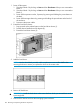


1. Install the replacement front bezel with the handle at a 90 degree angle making sure the
bottom pins are aligned with the bottom holes (1), and replace the screws into the front bezel
(2).
NOTE: There are two screws on the bottom, four screws on the sides (two on each side),
and two screws hidden behind the handle.
2. Push the drive drawer back into the messaging system enclosure.
3. Power on the messaging system.
4. Verify that the replacement component is working properly by checking the associated LED
status.
5. Confirm the system has resumed normal operations.
Removing and replacing the front bezel (full)
NOTE: This full procedure is only required if all screws are not accessible due to the position of
the messaging system in the rack.
This section describes how to fully remove and replace the front bezel in the messaging system.
Removing the front bezel (full)
To remove the front bezel:
1. To power off the system:
1. Shut down blade 2 by clicking on Start and then Shut Down while you are connected to
blade 1.
2. Shut down blade 1 by clicking on Start and then Shut Down while you are connected to
blade 2.
3. Power off the expansion nodes, if present, by pressing and holding the power button at
the back.
4. Power off the storage solution by pressing and holding the power button at the back of
the enclosure.
5. Disconnect the power cables.
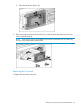
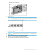
2. Extend the hard drive drawer:
1. Press upward on the release button on the hard drive drawer (1).
2. Pull the drawer handle down 90 degrees (2).
108 Removing and replacing hardware components