
Administrator's Guide
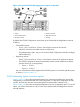
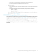

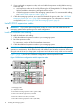
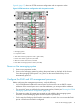
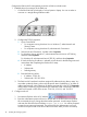
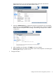
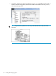

Figure 8 (page 17) shows an E5700 maximum configuration with 4 expansion nodes.
Figure 8 E5700 maximum configuration with 4 expansion nodes
1. Messaging System
2–5. Expansion nodes
6. SAS cable connecting expansion node 1 (green cable)
7. Green color code for upper SAS I/O module
8. Red color code for lower SAS I/O module
9. SAS cable connecting expansion node 2 (red cable)
Power on the messaging system
1. Power on any expansion nodes.
2. Power on the messaging system by pushing the power button on the back of the chassis.
Once the messaging system power is on, power on the server blades if they do not
automatically power on.
Configure the EMU and iLO management processors
Before configuring the management processors, verify the following:
• You have determined whether the network ports on the server are to use DHCP or static
addresses. If the network ports are to use static addresses, you must provide the addresses.
• The server NIC ports are cabled to the appropriate switches/VLANs (see“Planning the E5300
Messaging System network configuration” (page 10)).
• The expansion nodes (if present) are powered up and cabled to the messaging system
enclosure, and the messaging system enclosure system is powered up.
• For this step, the EMU port should not be connected to a switch. You can connect the EMU
port to a switch once the EMU is configured.
Power on the messaging system 17