Hardware Reference Guide HP Elite 7100 Series Microtower PCs
© Copyright 2009 Hewlett-Packard Development Company, L.P. The information contained herein is subject to change without notice. Microsoft, Windows, and Windows Vista are either trademarks or registered trademarks of Microsoft Corporation in the United States and/or other countries. The only warranties for HP products and services are set forth in the express warranty statements accompanying such products and services. Nothing herein should be construed as constituting an additional warranty.
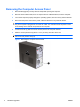
About This Book This guide provides basic information for upgrading these computer models. The model illustrated in this guide may look different than your computer model. WARNING! Text set off in this manner indicates that failure to follow directions could result in bodily harm or loss of life. CAUTION: Text set off in this manner indicates that failure to follow directions could result in damage to equipment or loss of information.
iv About This Book ENWW
Table of contents Hardware Upgrades ............................................................................................................................................ 1 Warnings and Cautions ........................................................................................................................ 1 Additional Information ........................................................................................................................... 1 Removing the Computer Access Panel ...
Optical Drive Precautions ................................................................................................................... 37 Operation ........................................................................................................................... 37 Cleaning ............................................................................................................................. 37 Safety .....................................................................................
Hardware Upgrades Warnings and Cautions Before performing upgrades be sure to carefully read all of the applicable instructions, cautions, and warnings in this guide. WARNING! To reduce the risk of personal injury from electrical shock, hot surfaces, or fire: Disconnect the power cord from the wall outlet and allow the internal system components to cool before touching. Do not plug telecommunications or telephone connectors into the network interface controller (NIC) receptacles.
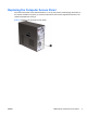
Removing the Computer Access Panel 1. Remove/disengage any security devices that prohibit opening the computer. 2. Remove all removable media, such as compact discs or USB flash drives, from the computer. 3. Turn off the computer properly through the operating system, then turn off any external devices. 4. Disconnect the power cord from the power outlet and disconnect any external devices.
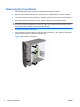
Replacing the Computer Access Panel Place the access panel on the chassis with about 1.3 cm (1/2 inch) of the panel hanging off the back of the chassis and slide it into place (1). Ensure that the hole for the screw is aligned with the hole in the chassis and tighten the screw (2).
Removing the Front Bezel 1. Remove/disengage any security devices that prohibit opening the computer. 2. Remove all removable media, such as compact discs or USB flash drives, from the computer. 3. Turn off the computer properly through the operating system, then turn off any external devices. 4. Disconnect the power cord from the power outlet and disconnect any external devices.
Removing Bezel Blanks On some models, there are bezel blanks covering the 3.5-inch and 5.25-inch external drive bays that need to be removed before installing a drive. 1. Remove the front bezel. 2. To remove the lower 5.25-inch bezel blank, gently twist and pull on the bezel blank until it breaks free from the front bezel (1), then discard the bezel blank. If the blank needs to be replaced at a later date, you can order a replacement blank from HP. 3. To remove the 3.
Replacing the Front Bezel Insert the three hooks on the left side of the bezel into the slots on the chassis (1) and rotate the bezel on from left to right (2) so that it snaps in place.
Installing Additional Memory The computer comes with double data rate 3 synchronous dynamic random access memory (DDR3SDRAM) dual inline memory modules (DIMMs). DIMMs The memory sockets on the system board can be populated with up to four industry-standard DIMMs. The memory sockets are populated with at least one preinstalled DIMM. To achieve the maximum memory support, you can populate the system board with up to 8GB of memory.
Installing DIMMs CAUTION: You must disconnect the power cord and wait approximately 30 seconds for the power to drain before adding or removing memory modules. Regardless of the power-on state, voltage is always supplied to the memory modules as long as the computer is plugged into an active AC outlet. Adding or removing memory modules while voltage is present may cause irreparable damage to the memory modules or system board. The memory module sockets have gold-plated metal contacts.
7. Open both latches of the memory module socket (1), and insert the memory module into the socket (2). NOTE: Populate the DIMM slots in the following order: DIMM2 (blue) , DIMM4 (blue), DIMM1 (black), then DIMM3 (black). Install larger size modules first, then smaller size modules (for example, 2GB first, then 1GB or 512MB). Figure 6 Installing a DIMM NOTE: A memory module can be installed in only one way. Match the notch on the module with the tab on the memory socket. 8.
Removing or Installing an Expansion Card The computer has three PCI Express x1 expansion slots and one PCI Express x16 expansion slot. The expansion slots accommodate full-height or half-height expansion cards. NOTE: You can install a PCI Express x1, x4, x8, or x16 expansion card in the PCI Express x16 expansion slot. To remove, replace, or add an expansion card: 1. Remove/disengage any security devices that prohibit opening the computer. 2.
NOTE: Before removing an installed expansion card, disconnect any cables that may be attached to the expansion card. a. If you are installing an expansion card in a vacant socket, you must slide one of the expansion slot covers up and out of the chassis or use a flatblade screwdriver to pry out one of the metal shields on the rear panel that covers the expansion slot. Be sure to remove the appropriate shield for the expansion card you are installing. Figure 8 Removing an Expansion Slot Cover b.
c. If you are removing a PCI Express x16 card, pull the retention arm on the back of the expansion socket away from the card and carefully rock the card back and forth until the connectors pull free from the socket. Be sure not to scrape the card against the other components. Figure 10 Removing a PCI Express x16 Expansion Card 9. Store the removed card in anti-static packaging. 10. If you are not installing a new expansion card, install an expansion slot cover to close the open slot.
11. To install a new expansion card, hold the card just above the expansion socket on the system board then move the card toward the rear of the chassis so that the bottom of the bracket on the card slides into the small slot on the chassis. Press the card straight down into the expansion socket on the system board. Figure 11 Installing an Expansion Card NOTE: When installing an expansion card, press firmly on the card so that the whole connector seats properly in the expansion card slot. 12.
16. Lock any security devices that were disengaged when the access panel was removed. 17. Reconfigure the computer, if necessary. Refer to the Computer Setup (F10) Utility Guide for instructions on using Computer Setup. Drive Positions NOTE: Your computer model may look different than the model shown below. Figure 13 Drive Positions 1 Two 5.25-inch external drive bays for optional drives (optical drives shown) 2 One 3.
Installing Additional Drives When installing additional drives, follow these guidelines: ● The primary Serial ATA (SATA) hard drive must be connected to the dark blue primary SATA connector on the system board. ● Connect a secondary Serial ATA (SATA) hard drive to the white SATA connector on the system board. ● Connect the first SATA optical drive to the light blue SATA connector on the system board. ● Connect a second SATA optical drive to the orange SATA connector on the system board.
CAUTION: To prevent loss of work and damage to the computer or drive: If you are inserting or removing a drive, shut down the operating system properly, turn off the computer, and unplug the power cord. Do not remove a drive while the computer is on or in standby mode. Before handling a drive, ensure that you are discharged of static electricity. While handling a drive, avoid touching the connector.
6. Disconnect the power cable (1) and data cable (2) from the rear of the optical drive. CAUTION: On some models you must press down on the latch on top of the power and data cables when disconnecting the cables from the drive. Failure to press down on the latch can damage the cable connectors. Figure 15 Disconnecting the Power and Data Cables 7. Remove the two screws that secure the drive to the drive cage (1), then slide the drive out of the front of the chassis (2).
Installing an Optical Drive into the 5.25-inch Drive Bay To install an optional 5.25-inch optical drive: 1. Remove/disengage any security devices that prohibit opening the computer. 2. Remove all removable media, such as compact discs or USB flash drives, from the computer. 3. Turn off the computer properly through the operating system, then turn off any external devices. 4. Disconnect the power cord from the power outlet and disconnect any external devices.
10. If the system configuration includes only one optical drive, connect the SATA data cable to the light blue system board connector. If you are adding a second optical drive, connect the SATA data cable to the orange system board connector. 11. Connect the power cable (1) and data cable (2) to the rear of the optical drive. Figure 18 Connecting the Power and Data Cables 12. Replace the front bezel and access panel. 13. Reconnect the power cord and turn on the computer. 14.
7. Remove the two retainer screws that secure the drive to the bay (1) then slide the drive forward and out of the bay (2). Figure 19 Removing a 3.5-inch Device (Media Card Reader Shown) Installing a Drive into the 3.5-inch External Drive Bay 1. Remove/disengage any security devices that prohibit opening the computer. 2. Remove all removable media, such as compact discs or USB flash drives, from the computer. 3.
9. Slide the drive in through the front of the chassis (1) until the bezel on the drive is evenly aligned with the computer front bezel and install the two M3 metric retainer screws (2) as shown in the illustration below. NOTE: Extra drive retainer screws are provided on the interior of the front bezel if needed. The M3 metric retainer screws for media card readers are black. Refer to Installing Additional Drives on page 15 for an illustration of the retainer screws location. Figure 20 Installing a 3.
Removing an Internal 3.5-inch Hard Drive NOTE: Before you remove the old hard drive, be sure to back up the data from the old hard drive so that you can transfer the data to the new hard drive. 1. Remove/disengage any security devices that prohibit opening the computer. 2. Remove all removable media, such as compact discs or USB flash drives, from the computer. 3. Turn off the computer properly through the operating system, then turn off any external devices. 4.
7. Push down the latch on the side of the hard disk drive cage (1), then slide the hard disk drive cage away from the bottom of the chassis (2) as shown below. Figure 22 Releasing the Hard Drive Cage 8. Lift the hard disk drive cage out of the chassis.
9. Disconnect the power cable (1) and data cable (2) from the back of the hard drive. CAUTION: On some models you must press down on the latch on top of the power and data cables when disconnecting the cables from the drive. Failure to press down on the latch can damage the cable connectors. Figure 24 Disconnecting the Hard Drive Cables 10. Remove the four screws that secure the hard disk drive to the hard disk drive cage (1), then slide the hard disk drive out of the hard disk drive cage (2).
Installing an Internal 3.5-inch Hard Drive 1. Follow the steps in Removing an Internal 3.5-inch Hard Drive on page 22 to remove the hard drive cage and, if necessary, the existing hard drive. 2. Slide the new drive into the hard disk drive cage (1), aligning the drive with the four screw holes on the cage. Install the four 6-32 standard screws that secure the hard disk drive to the hard disk drive cage (2). Make sure the hard disk drive cables are facing the top of the drive cage.
3. Connect the power cable (1) and data cable (2) to the back of the hard drive. Figure 27 Connecting the Hard Drive Cables CAUTION: Never crease or bend a SATA data cable tighter than a 30 mm (1.18 in) radius. A sharp bend can break the internal wires. 4. Place the hard disk drive cage into the chassis (1), then slide it down toward the bottom of the chassis until it locks into place (2).
5. Attach the two screws that secure the hard disk drive cage to the chassis. Figure 29 Securing the Hard Drive Cage 6. If installing a new drive, connect the opposite end of the data cable to the appropriate system board connector. NOTE: If your system has only one SATA hard drive, you must connect the hard drive data cable to the dark blue SATA on the system board to avoid any hard drive performance problems.
Battery Replacement The battery that comes with the computer provides power to the real-time clock. When replacing the battery, use a battery equivalent to the battery originally installed in the computer. The computer comes with a 3-volt lithium coin cell battery. WARNING! The computer contains an internal lithium manganese dioxide battery. There is a risk of fire and burns if the battery is not handled properly. To reduce the risk of personal injury: Do not attempt to recharge the battery.
Type 1 a. Lift the battery out of its holder. Figure 30 Removing a Coin Cell Battery (Type 1) b. Slide the replacement battery into position, positive side up. The battery holder automatically secures the battery in the proper position. Type 2 a. To release the battery from its holder, squeeze the metal clamp that extends above one edge of the battery. When the battery pops up, lift it out (1). b.
b. Insert the new battery and position the clip back into place. Figure 32 Removing a Coin Cell Battery (Type 3) NOTE: After the battery has been replaced, use the following steps to complete this procedure. 8. Replace the computer access panel. 9. Plug in the computer and turn on power to the computer. 10. Reset the date and time, your passwords, and any special system setups using Computer Setup. 11. Lock any security devices that were disengaged when the access panel was removed.
Installing a Security Lock The security locks displayed below and on the following pages can be used to secure the computer.
HP Business PC Security Lock 1. Fasten the security cable by looping it around a stationary object. Figure 35 Securing the Cable to a Fixed Object 2. Thread the keyboard and mouse cables through the lock.
3. Screw the lock to the chassis using the screw provided. Figure 37 Attaching the Lock to the Chassis 4. Insert the plug end of the security cable into the lock (1) and push the button in (2) to engage the lock. Use the key provided to disengage the lock.
HP Chassis Security Kit An optional HP Chassis Security Kit prevents computer components from being removed through an open optical drive bay.
A Electrostatic Discharge A discharge of static electricity from a finger or other conductor may damage system boards or other static-sensitive devices. This type of damage may reduce the life expectancy of the device. Preventing Electrostatic Damage To prevent electrostatic damage, observe the following precautions: ● Avoid hand contact by transporting and storing products in static-safe containers.
B Computer Operating Guidelines, Routine Care and Shipping Preparation Computer Operating Guidelines and Routine Care Follow these guidelines to properly set up and care for the computer and monitor: 36 ● Keep the computer away from excessive moisture, direct sunlight, and extremes of heat and cold. ● Operate the computer on a sturdy, level surface. Leave a 10.2-cm (4-inch) clearance on all vented sides of the computer and above the monitor to permit the required airflow.
Optical Drive Precautions Be sure to observe the following guidelines while operating or cleaning the optical drive. Operation ● Do not move the drive during operation. This may cause it to malfunction during reading. ● Avoid exposing the drive to sudden changes in temperature, as condensation may form inside the unit. If the temperature suddenly changes while the drive is on, wait at least one hour before you turn off the power. If you operate the unit immediately, it may malfunction while reading.
Index A access panel removing 2 replacing 3 B battery replacement 28 C chassis security kit 34 computer operating guidelines 36 connecting drive cables 15 D DIMMs.