
Maintenance and Service Guide


Table Of Contents
- Product description
- External component identification
- Illustrated parts catalog
- Removal and replacement procedures
- Preliminary replacement requirements
- Component replacement procedures
- Bottom cover
- Rear cover
- Hard drive
- Memory module
- Y-axis capacitor board
- RTC battery
- USB board
- X-axis capacitor board
- Converter board
- Media card reader board
- USB connector cable
- Speakers
- Display stand recess
- Power button board
- Battery
- Webcam/microphone module
- Audio/USB board
- WLAN module
- Air flow channel
- Display panel cable
- Fan
- System board
- Heat sink
- Display stand
- Wireless antenna
- Middle frame
- Power connector cable
- Using Setup Utility (BIOS) and HP PC Hardware Diagnostics (UEFI)
- Specifications
- Backing up, restoring, and recovering
- Power cord set requirements
- Recycling
- Index
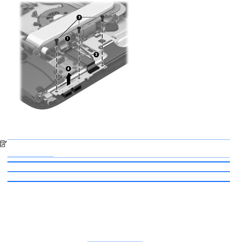
Remove the USB board:
1. Release the ZIF connector (1) to which the USB board ribbon cable is attached, and then
disconnect the USB board ribbon cable from the system board.
2. Detach the USB board ribbon cable (2) from the middle frame. (The USB board ribbon cable is
attached to the middle frame with double-sided adhesive.)
3. Remove the three Phillips PM3.0×6.5 screws (3) that secure the USB board to the
display assembly.
4. Remove the USB board (4) and cable.
Reverse this procedure to install the USB board.
X-axis capacitor board
NOTE: The X-axis capacitor board spare part kit does not include the X-axis capacitor board cable.
The X-axis capacitor board cable is included in the Cable Kit, spare part number 728048-001. See
Cable Kit on page 12 for more Cable Kit information.
Description Spare part number
X-axis capacitor board 728067-001
Before removing the X-axis capacitor board, follow these steps:
1. Turn off the computer. If you are unsure whether the computer is off or in Hibernation, turn the
computer on, and then shut it down through the operating system.
2. Disconnect the power from the computer by unplugging the power cord from the computer.
3. Disconnect all external devices from the computer.
4. Remove the bottom cover (see
Bottom cover on page 23).
Component replacement procedures 33