
Maintenance and Service Guide


Table Of Contents
- Product description
- External component identification
- Illustrated parts catalog
- Removal and replacement procedures
- Preliminary replacement requirements
- Component replacement procedures
- Bottom cover
- Rear cover
- Hard drive
- Memory module
- Y-axis capacitor board
- RTC battery
- USB board
- X-axis capacitor board
- Converter board
- Media card reader board
- USB connector cable
- Speakers
- Display stand recess
- Power button board
- Battery
- Webcam/microphone module
- Audio/USB board
- WLAN module
- Air flow channel
- Display panel cable
- Fan
- System board
- Heat sink
- Display stand
- Wireless antenna
- Middle frame
- Power connector cable
- Using Setup Utility (BIOS) and HP PC Hardware Diagnostics (UEFI)
- Specifications
- Backing up, restoring, and recovering
- Power cord set requirements
- Recycling
- Index
5. Remove the rear cover (see Rear cover on page 26).
6. Disconnect the battery cable (see
Hard drive on page 27).
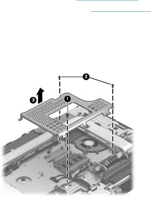
Remove the X-axis capacitor board:
1. Remove the Phillips PM3.0×4.5 screw (1) and the two Phillips PM3.0×6.5 screws (2) that secure
the cover bracket to the computer.
2. Remove the cover bracket (3).
The cover bracket is available using spare part number 728054-001.
3. Release the two ZIF connectors (1) to which the two display panel ribbon cables are attached,
and then disconnect the two display panel ribbon cables from the X-axis capacitor board.
4. Release the ZIF connector (2) to which the capacitor board ribbon cable is attached, and then
disconnect the capacitor board ribbon cable from the X-axis capacitor board.
5. Disconnect the X-axis capacitor board cable (3) from the system board.
6. Release the X-axis capacitor board cable from the clips (4) built into the middle frame.
7. Remove the two Phillips PM2.5×3.0 screws (5) that secure the X-axis capacitor board to the
middle frame.
34 Chapter 4 Removal and replacement procedures