
Maintenance and Service Guide


Table Of Contents
- Product description
- External component identification
- Illustrated parts catalog
- Removal and replacement procedures
- Preliminary replacement requirements
- Component replacement procedures
- Bottom cover
- Rear cover
- Hard drive
- Memory module
- Y-axis capacitor board
- RTC battery
- USB board
- X-axis capacitor board
- Converter board
- Media card reader board
- USB connector cable
- Speakers
- Display stand recess
- Power button board
- Battery
- Webcam/microphone module
- Audio/USB board
- WLAN module
- Air flow channel
- Display panel cable
- Fan
- System board
- Heat sink
- Display stand
- Wireless antenna
- Middle frame
- Power connector cable
- Using Setup Utility (BIOS) and HP PC Hardware Diagnostics (UEFI)
- Specifications
- Backing up, restoring, and recovering
- Power cord set requirements
- Recycling
- Index
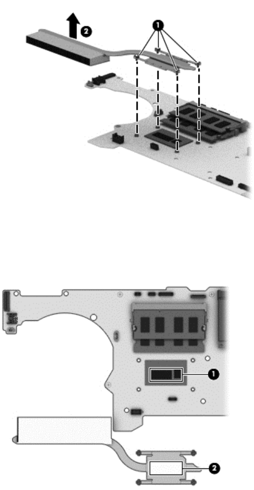
Remove the heat sink:
1. Loosen the four Phillips PM2.0×4.0 captive screws (1) that secure the heat sink to the
system board.
2. Remove the heat sink (2).
The thermal material must be thoroughly cleaned from the surfaces of the heat sink and the system
board components each time the heat sink is removed. Replacement thermal material is included with
the heat sink and system board spare part kits.
Thermal paste is used on the processor (1) and the heat sink section (2) that services it
Reverse this procedure to install the heat sink.
Component replacement procedures 57