HP Envy x2 Maintenance and Service Guide IMPORTANT! This document is intended for HP authorized service providers only.
© Copyright 2012 Hewlett-Packard Development Company, L.P. Intel is a trademark of Intel Corporation in the U.S. and other countries. Microsoft and Windows are U.S. registered trademarks of Microsoft Corporation. SD Logo is a trademark of its proprietor. The information contained herein is subject to change without notice. The only warranties for HP products and services are set forth in the express warranty statements accompanying such products and services.
Safety warning notice WARNING! To reduce the possibility of heat-related injuries or of overheating the device, do not place the device directly on your lap. Use the device only on a hard, flat surface. Do not allow another hard surface, such as an adjoining optional printer, or a soft surface, such as pillows or rugs or clothing, to block airflow. Also, do not allow the AC adapter to contact the skin or a soft surface, such as pillows or rugs or clothing, during operation.
iv Safety warning notice
Table of contents 1 Product description ........................................................................................................................................ 1 2 External component identification ................................................................................................................ 3 Tablet edge components ...................................................................................................................... 3 Display ..............................
Multimedia board ............................................................................................................... 33 Hinge assembly removal ................................................................................................... 34 Top cover with keyboard (includes) TouchPad module ..................................................... 35 System board .....................................................................................................................
Using the HP Recovery partition to recover a minimized image (select models only) ...................................................................................................... 71 Changing the boot order ................................................................................... 72 Removing the HP Recovery partition ................................................................................. 72 8 Power cord set requirements ...............................................................
viii
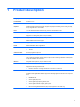
1 Product description Category Description Product Name HP ENVY x2 PC Processors Intel® Dual-Core™' Z2760 (1.8GHz, 592KB, L2) Graphics Intel® HD Graphics Media Accelerator. Supports HD playback streaming and recording at 1080p, 30 fps. Supports DX1 0.1 and HDMI. Panel 11.6" HD Aniti-Glare WLED UWVA 50%cg 400 nits LVDS Ultraslim 2.
Category Description Ports Tablet ● Docking connector (Power/USB). Supports charging, audio-out, and video out. ● Mic-in (combo) ● Audio-out (stereo headphone). Beats supported NOTE: Stand-alone microphones and headphones with separate microphone jacks are not supported. Keyboard dock Keyboard ● Mic-in (combo) ● Audio-out (stereo headphone). Beats supported ● HDMI version 1.4a supporting 1080p at 60Hz ● USB 2.
2 External component identification Tablet edge components Tablet edge components 3
Components (1) Description Power button ● When the computer is off, press the button to turn on the tablet. ● When the computer is on, press the button briefly to initiate Sleep. ● When the computer is in the Sleep state, press the button briefly to exit Sleep. CAUTION: Pressing and holding down the power button will result in the loss of unsaved information.
Components Description (8) System information Displays serial number, product number, warranty, and regulatory and wireless certification information. (9) Audio-out (headphone) jack/Audio-in (microphone) jack Connects optional powered stereo speakers, headphones, earbuds, a headset, or a television audio cable. WARNING! To reduce the risk of personal injury, adjust the volume before using headphones, earbuds, or a headset.
Display Component Description (1) WLAN antennas (2)* Send and receive wireless signals. (2) Internal microphones (2) Record audio, automatically filtering out the noise around you and cancelling echoes. (3) Webcam (front) Records video and takes still photographs. Swipe from the right edge of the TouchPad or touch screen to display the charms, tap Search, and then tap the search box. Type c, and then select Camera from the list of applications.
Component Description (8) With HP TouchZone, you can wirelessly connect, communicate and transfer data/info to and from your Near Field Communication (NFC)-compatible devices. Near Field Communication (NFC) antenna *The antennas are not visible from the outside of the computer. For optimal transmission, keep the areas immediately around the antennas and proximity sensors free from obstructions.
Keyboard dock Top Component Description (1) Alignment posts Align and attach the tablet to the keyboard dock. (2) Release latch Releases the tablet. To release the tablet, slide the release latch to the left. (3) Docking connector Connects the tablet to the keyboard dock. TouchPad Component (1) 8 Description TouchPad on/off button Chapter 2 External component identification Turns the TouchPad off or on when you double-tap the button.
Component Description (2) TouchPad zone Reads your finger gesture to move the pointer or activate items on the screen. (3) Left TouchPad button Functions like the left button of an external mouse. (4) Right TouchPad button Functions like the right button on an external mouse. Lights Component (1) (2) Description Caps lock light Mute light ● White: Caps lock is on. ● Off: Caps lock is off. ● Amber: Computer sound is off. ● Off: Computer sound is on.
Keys Component Description (1) esc key Displays system information when pressed in combination with the fn key. (2) fn Displays system information when pressed in combination with the esc key. (3) Windows button Returns you to the Start screen from an open app or the Windows desktop. NOTE: Pressing the Windows button again will return you to the previous screen. (4) b key Enables or disables Beats Audio when pressed in combination with the fn key. (5) Action keys Perform common tasks.
Component (1) Description Digital Media Slot Supports the following digital card formats: ● Secure Digital (SD) Memory Card ● Secure Digital Extended Capacity (SDxC) Memory Card ● Secure Digital High Capacity (SDHC) Memory Card ● Ultra High Speed MultiMediaCard (UHS/MMC) (2) USB 2.0 port Connects an optional USB device. (3) Power connector Connects an AC adapter.
Left side Component Description (1) HDMI port Connects an optional video or audio device, such as a highdefinition television, any compatible digital or audio component, or a high-speed HDMI device. (2) USB 2.0 port Connects an optional USB device. (3) Audio-out (headphone) jack/Audio-in (microphone) jack Connects optional powered stereo speakers, headphones, earbuds, a headset, or a television audio cable. Also connects an optional headset microphone.
Releasing the tablet from the keyboard dock To release the tablet from the keyboard dock, follow these steps: 1. Slide the release latch on the keyboard dock to the left (1). 2. Lift and remove the tablet (2).
3 Illustrated parts catalog Locating system information Important system information is located on the bottom edge of the tablet.
Computer major components Item Component Spare part number (1) Touch screen (with cables) 702353-001 Computer major components 15
16 Item Component Spare part number (2) Display panel 702362–001 (3) Display panel cable 702351 –001 (4) NFC antenna 702347-001 (5) System board (includes keyboard cable): 64 (GB) 702366–001 64 (GB) W8 Standard 702366–501 64 (GB) W8 Pro 702366–601 128 (GB) 708759–001 128 (GB) W8 Standard 708759–501 128 (GB) W8 Pro 708759–601 (6) TouchScreen connector board (with cable) 702351-001 (7) Battery (with cable) 2–cell 25W Hr 3.38AH battery (Tablet) 694501–001 2–cell 21W Hr 2.
Keyboard dock parts Item Component (1) Top cover/keyboard Spare part number Top cover with keyboard for use in the United States 702369-001 Top cover with keyboard for use in the United Kingdom and Singapore 702369-031 Top cover with keyboard for use in Germany 702369-041 Top cover with keyboard for use in France 702369-051 Top cover with keyboard for use in Italy 702369-061 Top cover with keyboard for use in Spain 702369-071 Top cover with keyboard for use in Portugal 702369-131 Keyboar
Item Component Spare part number Top cover with keyboard for use in Turkey 702369-141 Top cover with keyboard for use in Greece 702369-151 Top cover with keyboard for use in Latin America 702369-161 Top cover with keyboard for use in Saudi Arabia 702369–171 Top cover with keyboard for use in Russia 702369–251 Top cover with keyboard for use in Thailand 702369–281 Top cover with keyboard for use in Japan 702369–291 Top cover with keyboard for use in Belgium 702369–A41 Top cover with keyboa
Sequential part number listing Spare part number Description 490371–001 Power Cord for use in North America 490371–011 Power Cord for use in Australia 490371–021 Power Cord for use in Europe, the Middle East and Africa 490371–031 Power Cord for use in the United Kingdom and Singapore 490371–061 Power Cord for use in Italy 490371–081 Power Cord for use in Denmark 490371–111 Power Cord for use in Switzerland 490371–201 Power Cord for use in Thailand 490371–291 Power Cord for use in Japan 4
20 Spare part number Description 702352–171 Keyboard dock for use in Saudi Arabia 702352-251 Keyboard dock for use in Russia 702352–A41 Keyboard dock for use in Belgium 702352–B31 Keyboard dock for use in The Netherlands 702352–BG1 Keyboard dock for use in Switzerland 702352–DB1 Keyboard dock for use in Canada 702352–DH1 Keyboard dock for use in Denmark, Finland, Norway 702353–001 Touch screen 702354–001 Display hinge assembly 702355–001 11.
Spare part number Description 702366–601 System board for use only with 64–GB W8 Pro models equipped with an Intel Z2760 1.
22 Spare part number Description 708758–AA1 11.6-in, HD, Anti-Glare WLED display panel for use with 128–GB units in People's Republic of China 708758–AB1 11.6-in, HD, Anti-Glare WLED display panel for use with 128–GB units in Taiwan 708758–AC1 11.6-in, HD, Anti-Glare WLED display panel for use with 128–GB units in Hong Kong 708758–D11 11.6-in, HD, Anti-Glare WLED display panel for use with 128–GB units in Chile 708758–D61 11.
4 Removal and replacement procedures CAUTION: This computer does not have user-replaceable parts. Only HP authorized service providers should perform the removal and replacement procedures described here. Accessing the internal part could damage the computer or void the warranty.
Drive handling CAUTION: Drives are fragile components that must be handled with care. To prevent damage to the computer, damage to a drive, or loss of information, observe these precautions: Before removing or inserting a hard drive, shut down the computer. If you are unsure whether the computer is off or in Hibernation, turn the computer on, and then shut it down through the operating system. Before handling a drive, be sure that you are discharged of static electricity.
Typical electrostatic voltage levels Relative humidity Event 10% 40% 55% Walking across carpet 35,000 V 15,000 V 7,500 V Walking across vinyl floor 12,000 V 5,000 V 3,000 V Motions of bench worker 6,000 V 800 V 400 V Removing DIPS from plastic tube 2,000 V 700 V 400 V Removing DIPS from vinyl tray 11,500 V 4,000 V 2,000 V Removing DIPS from Styrofoam 14,500 V 5,000 V 3,500 V Removing bubble pack from PCB 26,500 V 20,000 V 7,000 V Packing PCBs in foam-lined box 21,000 V 11,0
Packaging and transporting guidelines Follow these grounding guidelines when packaging and transporting equipment: ● To avoid hand contact, transport products in static-safe tubes, bags, or boxes. ● Protect ESD-sensitive parts and assemblies with conductive or approved containers or packaging. ● Keep ESD-sensitive parts in their containers until the parts arrive at static-free workstations. ● Place items on a grounded surface before removing items from their containers.
Equipment guidelines Grounding equipment must include either a wrist strap or a foot strap at a grounded workstation. ● When seated, wear a wrist strap connected to a grounded system. Wrist straps are flexible straps with a minimum of one megohm ±10% resistance in the ground cords. To provide proper ground, wear a strap snugly against the skin at all times. On grounded mats with banana-plug connectors, use alligator clips to connect a wrist strap.
Base enclosure Description Spare part number Base enclosure (Black) 702349-001 Rubber feet 702363-001 Before disassembling the keyboard dock, follow these steps: 1. Shut down the keyboard dock. If you are unsure whether the computer is off or in Hibernation, turn the computer on, and then shut it down through the operating system. 2. Disconnect all external devices connected to the computer. 3.
4. Separate and release the bottom enclosure (1), and then remove the bottom enclosure (2). Battery Description Spare part number 2-cell, 25WHr 3.38AH Li-ion battery (Tablet) 694501-001 2-cell, 21WHr 2.86AH Li-ion battery (Keyboard dock) 694502-001 Before removing the battery, follow these steps: 1. Shut down the computer. If you are unsure whether the computer is off or in Hibernation, turn the computer on, and then shut it down through the operating system. 2.
3. 30 Remove the battery (3).
Digital media card reader board Description Spare part number Digital media card reader 702359-001 Before removing the digital media card reader, follow these steps: 1. Shut down the computer. If you are unsure whether the computer is off or in Hibernation, turn the computer on, and then shut it down through the operating system. 2. Disconnect all external devices connected to the computer. 3.
USB/Power Connector board Description Spare part number USB/Power Connector board 702360-001 Before removing the USB/Power connector board, follow these steps: 1. Shut down the computer. If you are unsure whether the computer is off or in Hibernation, turn the computer on, and then shut it down through the operating system. 2. Disconnect all external devices connected to the computer. 3.
Multimedia board Description Spare part number Multimedia board 702361-001 Before removing the multimedia board (which includes USB, Audio, and HDMI connectors), follow these steps: 1. Shut down the computer. If you are unsure whether the computer is off or in Hibernation, turn the computer on, and then shut it down through the operating system. 2. Disconnect all external devices connected to the computer. 3.
Hinge assembly removal Description Spare part number Hinge assembly 702354-001 Before removing the hinge, follow these steps: 1. Shut down the computer. If you are unsure whether the computer is off or in Hibernation, turn the computer on, and then shut it down through the operating system. 2. Disconnect all external devices connected to the computer. 3. Disconnect the power from the computer by first unplugging the power cord from the AC outlet and then unplugging the AC adapter from the computer.
Top cover with keyboard (includes) TouchPad module Description Spare part number TouchPad board (includes cable) 702368-001 Top cover with keyboard for use in the United States 702369-001 Top cover with keyboard for use in the United Kingdom and Singapore 702369-031 Top cover with keyboard for use in Germany 702369-041 Top cover with keyboard for use in France 702369-051 Top cover with keyboard for use in Italy 702369-061 Top cover with keyboard for use in Spain 702369-061 Top cover with key
Remove the TouchPad button board and cable: 1. Turn the top cover upside down, with the back edge toward you. 2. Disconnect the TouchPad cable (1) and release the metal tape (2). 3. Remove the two Phillips PM screws, and then remove the TouchPad tab. 4. Remove the TouchPad. Reverse this procedure to install the TouchPad button board and cable.
System board NOTE: The system board spare part kit includes replacement thermal material. Description Spare part number For use only with computer models equipped with 64–GB devices 702366–001 For use only with W8 Standard computer models equipped with 64–GB devices 702366-501 For use only with W8 Pro computer models equipped with 64–GB devices 702366–601 System board for keyboard dock 702367–001 System board for use only with 64–GB models equipped with an Intel Z2760 1.
2. Remove the 5 Phillips PM 2.0x3.0 screws (1). 3. Remove the system board (2). Reverse this procedure to install the system board. Tablet parts The following sections show the removal and replacement procedures for the tablet parts.
NOTE: Any time the internal tablet components are repaired, the display bezel should be replaced.
Display panel assembly and Battery NOTE: When disassembling or assembling the display panel, it is necessary to operate in a clean environment such as a clean room or clean work table. 40 Description Spare part number 2–cell 25WHr 3.38 AH Li-ion battery 694501–001 11.6-in, HD, Anti-Glare WLED display panel for use in all regions 702362-001 11.6-in, HD, Anti-Glare WLED display panel for use with 64–GB units in Europe, the Middle East and Africa 702355-001 11.
Before removing the display panel, follow these steps: 1. Shut down the computer. If you are unsure whether the computer is off or in Hibernation, turn the computer on, and then shut it down through the operating system. 2. Disconnect all external devices connected to the computer. 3. Disconnect the power from the computer by first unplugging the power cord from the AC outlet and then unplugging the AC adapter from the computer. Remove the display panel: 1.
5. Release the touch screen. NOTE: Be careful not to scratch the screen. 6. 42 Remove the 5 2x3–mm screws securing the panel to the display assembly (2 on the top edge, 1 on the right side, and 2 on the left side).
7. Lift up on the top edge of the display. NOTE: Support the display panel as you are removing the screws. 8. Locate the NFC antenna connector (1), disconnect the NFC antenna cable (2), and then remove the NFC antenna (3).
9. Disconnect the tablet battery cable (1), remove the 4 screws that secure the battery (2), and then remove the tablet battery (3). 10. Release the display panel cable support strip (1), release the display panel cable tape (2), and then disconnect the display panel cable (3).
11. Clear the routing channel and clips (4), and then remove the display panel (5). 12. Locate the display panel cable support strip (1), release the display panel cable tape (2), and then disconnect the display panel cable (3).
13. Lift up on the right side of the screen. From the left side, locate the 2 connectors (1), and then release the connectors (2). Remove the touch screen (3) Reverse this procedure to install the display panel. System board Component Spare part number System board for use only with 128–GB tablet equipped with an Intel Z2760 1.8GHz processor (includes processor and replacement thermal material) 708759–001 System board (Windows 8 Standard) for use only with 128–GB tablet equipped with an Intel Z2760 1.
2. Disconnect the webcam light board cable (4), the power button board cable (5), and then disconnect the right speaker cable (6). 3. Disconnect the volume control button board cable (1), the micro Digital Media Card Reader board cable (2), and then disconnect the left speaker cable (3).
4. Disconnect the stabilizer module cable (4), disconnect the docking connector board cable (5), and then disconnect the touch screen connector board cable (6). 5. Remove the five screws securing the system board (1), and then remove the system board (2). Reverse this procedure to install the system board.
Touch screen connector board Description Spare part number Touch screen connector board 702351–001 Before removing the touch screen connector board, follow these steps: 1. Shut down the computer. If you are unsure whether the computer is off or in Hibernation, turn the computer on, and then shut it down through the operating system. 2. Disconnect all external devices connected to the computer. 3.
Before removing the display bezel, follow these steps: 1. Shut down the computer. If you are unsure whether the computer is off or in Hibernation, turn the computer on, and then shut it down through the operating system. 2. Disconnect all external devices connected to the computer. 3. Disconnect the power from the computer by first unplugging the power cord from the AC outlet and then unplugging the AC adapter from the computer. 4. Remove the base enclosure (see Base enclosure on page 28). 5.
5. Remove the ten screws securing the display bezel. 6. Release the bezel's bottom edge (1), release the left and right edges (2), release the top edge (3), and remove the display bezel (4). Reverse this procedure to install the display bezel. Webcam assembly (front) Description Spare part numbers Webcam assembly 702358-001 Before removing the webcam assembly: 1. Shut down the computer.
5. Remove the base enclosure (see Base enclosure on page 28). 6. Remove the display bezel (see Display bezel on page 49). Remove the front webcam assembly: 1. 52 Remove the 2 screws securing the webcam LED board (1) to the display bezel, and then remove the webcam LED board (2).
2. Remove the from webcam. 3. Remove the screw securing the microphone board (1), and then remove the board (2).
54 4. Locate the volume control button board connector (1), and then disconnect the volume control button board cable (2). Remove the two screws securing the volume control button board (3), and then remove the volume control button board (4). 5. Remove the rear cam.
Audio/micro SD digital media card reader/touch screen board Description Spare part number Audio/micro SD digital media card reader/touch screen board 702357–001 Before removing the Audio/micro SD digital media card reader/touch screen board, follow these steps: 1. Shut down the computer. If you are unsure whether the computer is off or in Hibernation, turn the computer on, and then shut it down through the operating system. 2. Disconnect all external devices connected to the computer. 3.
USB/Power button board Description Spare part number USB/Power button board 689944-001 Before removing the USB/Power button board, follow these steps: 1. Shut down the computer. If you are unsure whether the computer is off or in Hibernation, turn the computer on, and then shut it down through the operating system. 2. Disconnect all external devices connected to the computer. 3.
5. Disconnect the vibration module cable from the system board (1), release the vibration module cable from the routing clips (2), and then remove the vibration module and cable (3). Speakers Description Spare part number Speakers 702365-001 1. Shut down the computer. If you are unsure whether the computer is off or in Hibernation, turn the computer on, and then shut it down through the operating system. 2. Disconnect all external devices connected to the computer. 3.
3. Remove the Phillips PM screw securing the speaker to the system board (3), and then remove the speakers (4). Micro SD digital media board Description Spare part number Micro SD digital media board 702357-001 Before removing the micro SD digital media reader card, follow these steps: 58 1. Shut down the computer. If you are unsure whether the computer is off or in Hibernation, turn the computer on, and then shut it down through the operating system. 2.
Remove the top cover from the display: 1. To remove the micro SD digital media card, locate the micro SD digital media board cable (1), and then disconnect the cable (2). 2. Locate the micro SD digital media board release points (3), remove the 2 screws (4), and then remove the board (5). Power button board Description Spare part number Power button board 702360-001 Before removing the power button board, follow these steps: 1. Shut down the computer.
4. 60 To remove power button board , disconnect the power button board cable (1), and then remove the cable (2).
5 Setup Utility (BIOS) and System Diagnostics Using Setup Utility Setup Utility, or Basic Input/Output System (BIOS), controls communication between all the input and output devices on the system (such as disk drives, display, keyboard, mouse, and printer). Setup Utility includes settings for the types of peripherals installed, the startup sequence of the computer, and the amount of system and extended memory. NOTE: Use extreme care when making changes in Setup Utility.
Navigating and selecting in Setup Utility To navigate and select in Setup Utility, follow these steps: 1. 2. Turn on or restart the computer, and then press esc while the “Press the ESC key for Startup Menu” message is displayed at the bottom of the screen. ● To select a menu or a menu item, use the tab key and the keyboard arrow keys and then press enter, or use a pointing device to click the item.
Restoring factory settings in Setup Utility NOTE: Restoring defaults will not change the hard drive mode. To return all settings in Setup Utility to the values that were set at the factory, follow these steps: 1. Turn on or restart the computer, and then press esc while the “Press the ESC key for Startup Menu” message is displayed at the bottom of the screen. 2. Press f10 to enter Setup Utility. 3. Use the arrow keys to select Exit > Load Setup Defaults. 4. Follow the on-screen instructions. 5.
Determining the BIOS version To determine whether available BIOS updates contain later BIOS versions than those currently installed on the computer, you need to know the version of the system BIOS currently installed. BIOS version information (also known as ROM date and System BIOS) can be displayed by pressing fn+esc (if you are already in Windows) or by using Setup Utility. 1. Start Setup Utility (BIOS). 2. Use the arrow keys to select Main. 3.
4. Double-click the file that has an .exe extension (for example, filename.exe). The BIOS installation begins. 5. Complete the installation by following the on-screen instructions. NOTE: After a message on the screen reports a successful installation, you can delete the downloaded file from your hard drive. Using System Diagnostics System Diagnostics allows you to run diagnostic tests to determine if the computer hardware is functioning properly.
6 Specifications Computer specifications Metric U.S. Width 29.16 cm 11.48 in Depth 2.15 cm 8.46 in Height (front to back) 2.11 to 3.19 cm 0.83 to 1.26 in With 6-cell battery 1.60 kg 3.53 lb With 3-cell battery 1.46 kg 3.22 lb Dimensions Weight Input power Operating voltage and current 18.5 V dc @ 3.
Metric Contrast ratio 200:1 (typical) Brightness 200 nits (typical) U.S. Pixel resolution Pitch 0.197 mm × 0.197 mm Format 1366 × 768 Configuration RGB vertical stripe Backlight LED Character display 80 × 25 Total power consumption 2.0 W Viewing angle ±65° horizontal, ±50° vertical (typical) 11.
7 Backing up, restoring, and recovering Your computer includes tools provided by HP and the operating system to help you safeguard your information and retrieve it if you ever need to. These tools will help you return your computer to a proper working state or even back to the original factory state, all with simple steps.
If you need to correct a problem with a preinstalled application or driver, use the Drivers and Applications Reinstall option of HP Recovery Manager to reinstall the individual application or driver. ● From the Start screen on the keyboard dock, type recovery, select HP Recovery Manager, and then select Drivers and Applications Reinstall, and follow the on-screen instructions.
Using Windows Refresh for quick and easy recovery When your computer is not working properly and you need to regain system stability, the Windows Refresh option allows you to start fresh and keep what is important to you. IMPORTANT: Refresh removes any traditional applications that were not originally installed on the system at the factory. NOTE: During Refresh, a list of removed traditional applications will be saved so that you have a quick way to see what you might need to reinstall.
3. Click Change PC settings in the bottom-right corner of the screen, and then select General from the PC settings screen. 4. Under Remove everything and reinstall Windows, select Get started, and follow the onscreen instructions. Recovering using HP Recovery Manager HP Recovery Manager software allows you to recover the computer to its original factory state.
Changing the boot order If the computer does not restart in HP Recovery Manager, you can change the computer boot order, which is the order of devices listed in BIOS where the computer looks for startup information. You can change the selection for an optical drive or a USB flash drive. To change the boot order: 1. Insert the HP Recovery media you created. 2. Restart the computer. 3. Press and hold esc while the computer is restarting, and then press f9 for boot options. 4.
8 Power cord set requirements The wide-range input feature of the computer permits it to operate from any line voltage from 100 to 120 volts AC, or from 220 to 240 volts AC. The 3-conductor power cord set included with the computer meets the requirements for use in the country or region where the equipment is purchased. Power cord sets for use in other countries and regions must meet the requirements of the country or region where the computer is used.
74 Country/region Accredited agency Applicable note number Japan JIS 3 The Netherlands KEMA 1 New Zealand SANZ 1 Norway NEMKO 1 The People's Republic of China CCC 4 Saudi Arabia SASO 7 Singapore PSB 1 South Africa SABS 1 South Korea KTL 5 Sweden SEMKO 1 Switzerland SEV 1 Taiwan BSMI 6 Thailand TISI 1 The United Kingdom ASTA 1 The United States UL 2 1. The flexible cord must be Type HO5VV-F, 3-conductor, 0.75-mm² conductor size.
9 Recycling When a non-rechargeable or rechargeable battery has reached the end of its useful life, do not dispose of the battery in general household waste. Follow the local laws and regulations in your area for battery disposal. HP encourages customers to recycle used electronic hardware, HP original print cartridges, and rechargeable batteries. For more information about recycling programs, see the HP Web site at http://www.hp.com/recycle.
Index Symbols/Numerics (webcam front), identifying 6 A AC adapter, spare part numbers 22 action keys identifying 10 antenna spare part numbers 19 audio board spare part numbers 20 audio, product description 1 audio-out (headphone) jacks 5, 12 B back up personal files 68 backups 68 base enclosure removal 28 spare part numbers 28 base enclosure, spare part number 19 battery removal 29 spare part numbers 18, 19, 20, 29 Beats Audio hotkey 10 bezel spare part numbers 19 bezel, display 49 Blu-ray ROM DVD±R/RW S
I integrated rear webcam, identifying 4, 6 internal microphones, identifying 6 J jacks audio-out (headphone) 5, 12 K keyboard product description 2 spare part numbers 16 keyboard dock spare part numbers 19, 20 keys action 10 esc 10 Windows button 10 L labels serial number 14 lights caps lock 9 mute 9 webcam 4, 6 M mass storage device precautions 24 spare part numbers 17 memory module product description 1 micro SD media board removal 58 microphone product description 1 minimized image creating 71 minimized
top cover spare part numbers 21 touch screen spare part numbers 20 TouchPad buttons 9 identifying 8 TouchPad button board removal 35 spare part number 35 TouchPad LED board spare part numbers 21 TouchPad on/off button, identifying 8 TouchPad zone, identifying 9 transporting guidelines 26 U USB 2.