
HP Compaq dx 7200 and dc7600 Personal Computers, Technical Reference Guide, 1st Edition

Technical Reference Guide www.hp.com 2-15
System Overview
2.3.3 Board Layouts
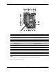
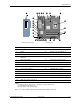
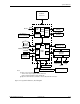
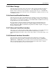
Figures 2-11 through 2-13 show the system and expansion boards for these systems. Figure the
2-9 shows the layout for the USDT systems board, which is a custom board specifically designed
for that particular form factor.
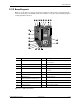
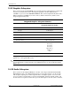
Figure 2-11. USDT System Board
Item Description Item Description
1 Hood sense header 11 Power button, power LED, HD LED, temp
sensor header
2 Serial port option header 12 Chassis speaker connector
3 Parallel port option header 13 Front panel audio connector
4 CMOS clear button 14 Chassis fan, secondary Front panel USB port
connector
5 SATA #0 header 15 Chassis fan connector
6 Password clear jumper header 16 Processor fan connctor
7 PCI Express x16
(ADD2/SDVO reversed layout) slot
17 DIMM sockets (3)
8 PCI 2.3 slot 18 MultiBay riser connector
9 Power supply (VccP) connector 19 Battery
10 Processor socket 20 Power supply connector
q
6
7
8
-
9
w
r
e
t
y
u
i
o
1
2
3
4
5
p