
HP Compaq dx 7200 and dc7600 Personal Computers, Technical Reference Guide, 1st Edition

Technical Reference Guide www.hp.com 2-17
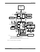
System Overview
NOTES:
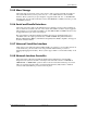
See CMT rear chassis illustration for externally accessible I/O connectors.
[1] Applicable to CMT chassis only.
[2] Not included on MT system boards.
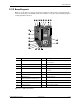
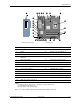
Figure 2-13. MT and CMT System Board and CMT PCI Expansion Board
Item Description Item Description
1 PCI 2.3 slots 15 SATA #2 connector (light blue) [2]
2 Battery 16 SATA #0 connector (dark blue)
3 PCI Express x1 slot 17 Hood lock header [2]
4 PCI Express x16 graphics/normal-layout
SDVO slot
18 Hood sense header [2]
5 Chassis fan header 19 Password clear jumper header
6 Power supply (VccP) connector 20 Power LED/button, HD LED header
7 Serial port B header [2] 21 CMOS clear switch
8 Processor socket 22 SATA #1 connector (white)
9 Processor fan connector 23 Internal speaker connector
10 DIMM sockets (4) 24 Auxiliary audio input connector
11 Power supply connector 25 Front panel USB port connector
12 Diskette drive connector 26 PCI expansion board connector [2]
13 Primary IDE (PATA) connector 27 Front panel audio connector
14 SATA #3 connector (orange) [2] -- --
1
q
2
3
4
5
6
7
8
-
9
w
e
d
f
g
h
z
j
k
l
r
t
y
u
i
p
o
a
s
System BoardPCI Expansion Board [1]
1