
e2400-160 Interface Controller


© 2003 Hewlett-Packard Company
First Edition (June 2003)
Part Number: 289158-002
*289158-002*
289158-002
configuration
Refer to the HP StorageWorks e2400-160 Fibre Channel Interface Controller User Guide for detailed procedures on
configuring the controller. For LUN mapping in OpenVMS or large SAN environments, refer to the HP StorageWorks
Fibre Channel Interface Controller Implementation Issues Application Note.
Note: If you are replacing a faulty controller, try to restore the old controller's configuration settings using the
FTP User Interface [ftp -> login -> bin -> put <path><filename>.cfg].
For All Configurations:
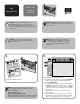
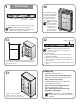
1. Cable up the serial interface and use your host application
to communicate over the serial bus. [Defaults: 115200
Bits per second, 8 Data bits, No Parity, 1 Stop bit, and
Xon/Xoff Flow Control]
2. Use the serial user interface to set the Ethernet configurations
(DHCP, IP address, Subnet, and Gateway.) [Perform
Configuration -> Ethernet and SNMP Configuration]
3. Save Configuration. [Perform Configuration -> Ethernet
and SNMP Configuration]
4. Reboot the controller. [Main Menu]
5. Document controller's IP address. [Perform Configuration
-> Ethernet and SNMP Configuration]
6. Enter the Visual User Interface by opening your web
browser and entering the controller's IP address.
[Defaults: Logon-root Password-password]
7. Set the Real-Time Clock. [System -> Real-Time Clock]
8. Set the Fibre Channel port Performance Mode for both fibre
ports. (1GB or 2GB, 2GB is the default, depending on the
hardware the controller is connected to. The controller is not
auto-switching.) [Ports -> FC Port 0 or FC Port 1]
9. Assign Port 0 Device Map to the FC Port 0 hosts or Port 1
Device Map to the FC Port 1 hosts that need to communicate
with the library or drives. [Mapping -> FC Port 0 or FC Port 1]
10. Select Port 0 Device Map or Port 1 Device Map and click
on Edit/View. [Mapping -> FC Port 0 or FC Port 1]
11. Set the Fill Map Priority to Bus/Target, and Fill Map. [Mapping
-> FC Port 0 or FC Port 1 -> Select Map -> Edit/View]
12. Since any device connected to any of the four SCSI buses
will be added, the device load should be distributed
between FC Port 0 and FC Port 1 for performance/load
balancing. Use Delete Map Item(s) to remove devices.
[Mapping -> FC Port 0 or FC Port 1 -> Select Map ->
Edit/View]
• If the fibre port is running at 2 GB performance configure
up to 2 SCSI Ultra 3 drives (e.g. Ultrium 460) per fibre
port, or up to 4 SCSI Ultra 2 drives (e.g. SDLT 220,
SDLT 320, and Ultrium 230) per fibre port.
• If the fibre port is running at 1 GB performance configure
up to 1 SCSI Ultra 3 drive (e.g. Ultrium 460) per fibre
port, or up to 2 SCSI Ultra 2 drives (e.g. SDLT 220,
SDLT 320, and Ultrium 230) per fibre port.
13. Active Fabric (AF) should be the last LUN used on the
map if there is an HP-UX host on the SAN. Do not move
AF to map LUN 0 (Device specific LUN=0 is normal).
[Mapping -> FC Port 0 or FC Port 1 -> Select Map ->
Edit/View]
14. Remove Gaps in the LUN sequence. [Mapping -> FC Port 0
or FC Port 1 -> Select Map -> Edit/View]
15. Repeat steps 9-14 so that both Port 0 Device Map and
Port 1 Device Map are assigned and configured.
16. Reboot the controller. [Reboot]
Additional Steps for Direct Connect
(Point to Point) Configurations:
1. Set Port Mode to Auto Sense. [[Ports -> FC Port 0 or FC Port 1]
2. Set Hard AL_PA to Enable. [Ports -> FC Port 0 or FC Port 1]
3. Click on Set AL_PA to select any available AL_PA. The
only other used AL_PA should be the host bus adapter
(HBA). Using a high number will help to avoid potential
conflicts. [Ports -> FC Port 0 or FC Port 1]
4. Repeat steps 1-3 so that both FC Port 0 and FC Port 1
are configured.
5. Reboot the controller. [Reboot]