
HP StorageWorks fixed universal load pack upgrade instructions (August 2002)

Fixed Universal Load Pack Upgrade Instructions
First Edition (August 2002)
Part Number: 308001-001
Hewlett-Packard Company
© Hewlett-Packard Company, 2002.
Hewlett-Packard Company makes no warranty of any kind with regard to
this material, including, but not limited to, the implied warranties of
merchantability and fitness for a particular purpose. Hewlett-Packard shall
not be liable for errors contained herein or for incidental or consequential
damages in connection with the furnishing, performance, or use of this
material.
This document contains proprietary information, which is protected by
copyright. No part of this document may be photocopied, reproduced, or
translated into another language without the prior written consent of
Hewlett-Packard. The information contained in this document is subject to
change without notice.
All other product names mentioned herein may be trademarks of their
respective companies.
Hewlett-Packard Company shall not be liable for technical or editorial
errors or omissions contained herein. The information is provided “as is”
without warranty of any kind and is subject to change without notice. The
warranties for Hewlett-Packard Company products are set forth in the
express limited warranty statements accompanying such products. Nothing
herein should be construed as constituting an additional warranty.
hp StorageWorks
fixed universal load pack
upgrade
instructions
open card completely before beginning
upgrade instructions
308001- 001
This document explains how to replace a removable SDLT/DLT
load pack with a fixed LTO/SDLT load pack in an ESL9198SL,
ESL9326SL, or ESL9595 library.
The upgrade procedure consists of the following steps:
1. Turn off library power.
2. Remove the existing load packs.
3. Install the fixed load pack.
4. Calibrate the fixed load pack.
You will need a Phillips screwdriver to perform this procedure.
NOTE: HP recommends that you use a magnetic-tipped screwdriver to avoid
dropping the screws.
Powering Off the Library
Before starting the upgrade procedure, turn off the library power:
1. On the graphical user interface (GUI) panel, press Standby to
place the library off-line.
The library robotics completes any current commands and then
stops.
2. Verify that the GUI displays System Off-line.
3. Press the Overview tab on the GUI.
4. In the Activity section of the Overview tab, verify that the
gripper contains a tape cartridge.
5. If the gripper contains a cartridge, perform a Move Cartridge
command to place it in an available bin.
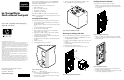
6. On the front of the library, locate the sliding panel that covers
the On/Off switch (see Figure 1).
7. The sliding panel is on the right front of the library, just below
the GUI.
8. Slide the panel open.
9. Set the On/Off switch to the off position.
Figure 1: On/Off switch
1 GUI 2 On/Off switch
10. Open the rear access door (ESL9198SL) or the left tape drive
access door (ESL9326SL/ESL9595).
11. Locate the AC power distribution assemblies in the rear lower
left corner of the cabinet.
12. On the top of the AC power distribution assemblies, set the
CB-1 switch 1 to the off position (see Figure 2).
Figure 2: AC power distribution assembly
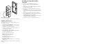
Removing the Existing Load Packs
To remove the existing load packs from the load port (see Figure 3):
1. Open the right front door (ESL9326SL/ESL9595) or the front
door (ESL9198SL) of the library.
2. Press up on the metal tab 1 at the upper right corner of the load
port bay.
3. Rotate the load pack handle 2 (at the top of the load pack)
forward and down.
4. Pull the load pack out of the load port.
5. Repeat steps 2 through 4 to remove the other load pack.
Figure 3: Removing the DLT/SDLT load packs
Installing the Fixed Load Packs
To install the two fixed load packs in the load port:
1. Install the two load port keys 1 on the right wall of the load
port as shown in Figure 4, using two of the screws provided in
the upgrade kit.
Figure 4: Installing the load port keys
2. Insert one of the fixed load packs into the load port, making
sure that tab in the load pack lines up with the mounting hole
1 in the load port.
Figure 5: Installing the load pack
3. Push the fixed load pack all the way to the left, then slide it
back into the load port until it stops.
4. Secure the fixed load pack in the load port using the screws 1
provided in the upgrade kit (see Figure 6).
1
2
1
1
2
1
1