
HP StorageWorks Interface Manager and Command View TL Installation Instructions (March 2005)
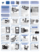

hp
StorageWorks
Interface
Manager and
Command View TL
Installation
Instructions
2
Power down the ESL9000 Series library.
a. Press Standby on the front control panel of the library
to place the library off-line. Verify that the control
panel indicates System Off-line.
b. Check the Overview screen of the control panel to
verify that the gripper is empty. If there is a tape
cartridge in the gripper, perform a move command to
place the cartridge in an available storage bin.
c. Switch off the power switch located below the control
panel.
1
Unpack the box and verify
that all the contents are present:
Successful operation of the Interface Manager card
requires a minimum of the following:
• HP StorageWorks ESL9000 Series Tape Library with
firmware revision 3.40 or later
• Interface Manager card and documentation
• One to four HP StorageWorks e2400-160 Fibre
Channel Interface Controllers with a minimum
firmware revision of 5.1.07
• Management station—a Microsoft Windows-based
PC (server)
You will need the following:
The HP StorageWorks Interface Manager for tape
libraries is a management card designed to consolidate
and simplify the management of multiple HP
StorageWorks e2400-160 Fibre Channel (FC) Interface
Controllers (FC-to-SCSI routers) installed in an HP
StorageWorks ESL library.
The Interface Manager card and the FC interface
controllers that it manages are installed in a cage. This
cage is installed into an HP StorageWorks ESL library.
Overview
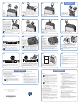
3
Note: If you
are adding an
Interface Manager
card to an existing
configuration, skip
to Step 22.
Open either the center
back access door or the
right back access door
of the library, depending on the model. Turn off both
circuit breakers on the AC power distribution assembly,
which is located in the base of the library cabinet behind
the rear access panel. Loosen the two captive screws at
the top of the electronics bay frame. Carefully tilt the
electronics bay outward.
Using a Phillips screwdriver, remove the four screws at
the corners of the top cover of the electronics bay, then
remove the cover. Place the screws in a safe place for
use later in the procedure.
4
Fan Installation
5
Using a Phillips screwdriver and the two screws that
you removed in Step 5, mount the fan assembly to the
upper right side of the electronics bay.
6
Feet
(Front of fan)
7
Push the electronics bay back
into the library and finger
tighten the two captive screws
at the top of the electronics
bay frame.
Using a Phillips screwdriver,
remove the six screws
securing the cover to the
electronics bay. Make sure
that you support the bottom
of the cover while
removing the screws.
8
Route the fan cable to the
right of any existing cards.
Caution:
The area for
the fan power
cable is limited.
Route the cable
as far back
on the electronics
bay as it will go.
This prevents the
cable from being
damaged when
the expansion
cage is installed.
9
Plug the fan assembly power cable into connector J14
on the robotics backplane.
J14
10
Expansion Cage
Installation
Caution: If you have not installed the cooling
fan for the expansion cage, refer to the previous
section, “Fan Installation,” to install the fan. To
prevent thermal damage to the equipment, do not install
the card cage without first installing the cooling fan.
Inspect the connector pins on the outside bottom of the
card cage. Make sure that no pins are bent or touching.
Caution: If a
connector pin is bent
or damaged, replace
the expansion cage.
Do not attempt to fix
the pin. A defective
pin can damage
the library.
Connector pins
(Bottom of expansion cage)
11
Guide Pins
(Front of electronics bay)
Loosen the two captive screws
at the top of the electronics
bay frame and carefully tilt the
electronics bay outward. Locate
the guide pins for alignment.
Lower the expansion cage into
the electronics bay into the guide
pin holes located on the PCI
backplane. Press down evenly
on both sides of the expansion
cage until it is firmly seated.
Caution: Be careful not to pinch the fan power cable.
Caution: Make sure that the connectors on the
expansion cage and the PCI backplane align
properly.
12
Using a Phillips
screwdriver, secure
the expansion cage
into the electronics
bay by replacing
the two rear cover
screws that you
removed in Step 4.
Note: Do
not replace
the two front
cover screws
yet.
13
If they are not already installed, install the cable clips
into each cable clamp starting with the first position
from the left edge of the clamp.
Note: The library rear door may not close if
clips are placed in the fourth and fifth openings
on the right edge of the cable clamp. If
necessary, use the extra clips with adhesive
backing and attach them to the left side of the
electronics bay frame.
Cable Clamp Installation
Install the upper cable clamp on the expansion cage
using the remaining two top cover screws.
14
15 16
Use a multimeter to measure the resistance shown on the
PCI backplane. Place one lead on ground and the other
lead on the +3.3V, +12V, and +5V test points to be
checked. If the multimeter shows a short, check the
expansion cage and fan to ensure proper connections.
Electronics
bay cover
Lower
cable clamp
Reinstall the
electronics bay
cover using the top
three screws only.
Install the lower
cable clamp on
the electronics bay
cover using the
bottom three screws.
17 18
With the SCSI ports
located to your left as
you face the back of
the library, align the
sides of the controller
with the guides in the
designated slot in the
expansion cage. Gently
push the controller into
the expansion cage
slot, ensuring that the
alignment pin on the
controller aligns with the alignment hole in the
corresponding cage slot. Push the controller until the
ejector handles engage the metal rails on the top of
the cage.
Push the ejector
handles so that
they extend
towards the
outer edges of
the FC interface
controller.
Fibre Channel Interface
Controller Installation
Caution: The expansion cage and the
expansion cards that it contains are not hot-
pluggable. To avoid damage to equipment and
possible loss of data, make sure that the library
is properly powered down, as described in
Step 2, before proceeding.
Caution: Parts can be damaged by
electrostatic discharge. Keep parts in their
containers until needed. Make sure that you are
properly grounded when touching static-sensitive
components.
Note: This poster outlines the first-time installation
procedure for the Interface Manager card. If you are
adding an Interface Manager card to an existing
configuration of one to four FC interface controllers, perform
Steps 2 and 3, then skip to Step 22 and finish the procedure.
Refer to the HP StorageWorks Interface Manager and
Command View TL Installation Guide for more information.
IMPORTANT:
If you are also installing one or more
HP StorageWorks e2400-160
Fibre Channel Interface Controllers
with the Interface Manager card,
use this documentation instead of the
installation instructions that come with
the Fibre Channel interface controllers.
Remove the screws that are attached to the fan and put
them in a safe place. Position the fan so that the feet
angle downward toward the holes in the side wall.
Position the fan cable against the side wall of the electronics
bay and drop it down through the opening in the floor of
the bay. Seat the fan by inserting the feet into the last row
of available holes on the electronics bay wall.
(Back of fan)
• Screwdrivers
(Phillips and flathead)
• Allen wrench
• Multimeter
• Anti-static wrist strap
• RJ-45 Ethernet cable
• PC or laptop (optional)
• IP address, subnet mask,
and gateway address
for Interface Manager
card (from Network
Administrator)