HP ElitePad 1000 G2 Maintenance and Service Guide for Thin Client systems IMPORTANT! This document is intended for HP authorized service providers only.
© Copyright 2014 Hewlett-Packard Development Company, L.P. Bluetooth is a trademark owned by its proprietor and used by Hewlett-Packard Company under license. Intel is a U.S. registered trademark of Intel Corporation. Microsoft and Windows are U.S. registered trademarks of Microsoft Corporation. SD Logo is a trademark of its proprietor. The information contained herein is subject to change without notice.
Safety warning notice WARNING! To reduce the possibility of heat-related injuries or of overheating the device, do not place the device directly on your lap or obstruct the device air vents. Use the device only on a hard, flat surface. Do not allow another hard surface, such as an adjoining optional printer, or a soft surface, such as pillows or rugs or clothing, to block airflow. Also, do not allow the AC adapter to contact the skin or a soft surface, such as pillows or rugs or clothing, during operation.
iv Safety warning notice
Table of contents 1 Product description ....................................................................................................................................... 1 2 External component identification ................................................................................................................. 3 Front ....................................................................................................................................................................... 3 Rear .
5 Removal and replacement procedures for Authorized Service Provider parts ................................................... 19 Tablet component replacement procedures ...................................................................................................... 19 Display assembly .............................................................................................................................. 19 WWAN module .............................................................................
1 Product description Category Description Product Name HP ElitePad 1000 G2 Processor Intel® Atom z3795 1.60-GHz processor (core burst up to 2.39-GHz), 1.60-GHz front-side bus (FSB), 2.0-MB L2 cache, up to 778-MHz graphics burst frequency, soldered to system board Graphics Intel HD Graphics Panel 10.1-in.
Category Description Power requirements Support for an HP ElitePad-proprietary 10-W AC adapter (3-wire, wall-mount and 2-wire, wallmount for use in Japan); connector on AC Adapter connects to the tablet through the docking connector Support for 2-cell, 30-Wh, 4.0-Ah, Li-ion battery Security Support for trusted platform module (TPM; Infineon TPM is SLB9656VQ1.2FW4.32) Operating system Preinstalled: Microsoft® Windows® Embedded 8.
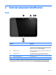
2 External component identification Front Component Description (1) Records video and captures still photographs. Front webcam To use the webcam, swipe from the right edge of the touch screen to display the charms, tap the Search icon, and then tap the search box. In the search box, type c, and then tap Camera. (2) WLAN antennas (2)* Send and receive wireless signals to communicate with wireless local area networks (WLAN).
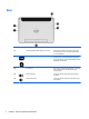
Rear Component 4 Description (1) Micro SD Card Reader/Micro SIM slot access hole Allows you to insert the end of a paper clip to open the access door to insert or remove a micro SD card or micro SIM module. (2) Memory card reader/Micro SIM slot Reads optional micro memory cards that store, manage, share, or access information. and supports an optional wireless micro subscriber identity module (SIM) (select models only).
Top Component (1) Description Audio-out (headphone) jack/Audio-in (microphone) jack Produces sound when connected to optional powered stereo speakers, headphones, earbuds, a headset, or television audio. Also connects an optional headset microphone. WARNING! To reduce the risk of personal injury, adjust the volume before putting on headphones, earbuds, or a headset. For additional safety information, see the Regulatory, Safety, and Environmental Notices.
Bottom Component Description (1) Speakers (2) Produce sound. (2) Product and regulatory information Displays product and regulatory information (select models only). (3) Docking connector Connects an AC adapter or an optional docking device. Service tag When ordering parts or requesting information, provide the tablet serial number and model number provided on the service tag.
Changing your tablet's settings Opening the Control Panel You can open the Control Panel using any of the following methods: ▲ Right-click the Windows icon on the taskbar and select Control Panel from the menu. TIP: A right-click can also be performed by touching and holding the desired location on the touch screen. ▲ Open the Charms bar and select Settings > Control Panel. ▲ On the Start screen, type Control Panel, and then click Control Panel when it appears in the search results.
1. Swipe from the right edge of the touch screen to display the charms, and then tap Settings. 2. Tap the screen icon to lock your current tablet screen in place and to prevent rotation. The icon displays a lock symbol when the autorotate lock is active. To turn off your tablet's autorotate lock feature: ▲ Slide the autorotate switch on the top edge of the tablet again. – or – 1. Swipe from the right edge of the touch screen to display the charms, and then tap Settings. 2.
3 Illustrated parts catalog NOTE: HP continually improves and changes product parts. For complete and current information on supported parts for your computer, go to http://partsurfer.hp.com, select your country or region, and then follow the on-screen instructions.
Item Component Spare part number (1) Display assembly (10.1-in.
Item Component Spare part number (17) Speakers (include left and right speakers and cables) 747629-001 (18) TXE board 753977-001 (19) Bottom case (includes the power button actuator and the slot cover and brackets) 747628-001 Power components Item Component (1) AC adapter (2) (3) Spare part number 10W, RC, V, 3-wire, wall mount 686120-001 10W, Non-PFC, non-Smart adapter, 2-wire, wall-mount (for use in Japan) 746156-001 40-W Smart AC adapter (RC, V, 3-wire) 693717-001 Duck head powe
Item Component Spare part number For use in India 490371-D61 For use in Israel 490371-BB1 For use in Italy 490371-061 For use in Japan 490371-291 For use in South Africa 490371-AR1 For use in South Korea 490371-AD1 For use in Taiwan 490371-AB1 For use in Switzerland 490371-111 For use in the United Kingdom 490371-031 For use in the United States 490371-001 Miscellaneous parts Component Spare part number HP ElitePad Service Tool (includes suction cup) 714222-001 HP ElitePad suction
Spare part number Description 490371-AR1 Power cord, 1.83 m (6 foot), for use in South Africa 490371-BB1 Power cord, 1.83 m (6 foot), for use in Israel 490371-D61 Power cord, 1.
14 Spare part number Description 755184-011 Duck head power adapter for use only in Australia 755184-021 Duck head power adapter for use only in Europe 755184-031 Duck head power adapter for use only in the United Kingdom and Singapore 755184-061 Duck head power adapter for use only in the Italy 755184-081 Duck head power adapter for use only in the Denmark 755184-371 Duck head power adapter for use only in the People's Republic of China 755184-AR1 Duck head power adapter for use only in Sou
4 Removal and replacement preliminary requirements Tools required You will need the following tools to complete the removal and replacement procedures: ● Magnetic screw driver ● Phillips P0 screw driver ● Plastic case utility tool Service considerations The following sections include some of the considerations that you must keep in mind during disassembly and assembly procedures.
An electronic device exposed to ESD may not be affected at all and can work perfectly throughout a normal cycle. Or the device may function normally for a while, then degrade in the internal layers, reducing its life expectancy. CAUTION: To prevent damage to the tablet when you are removing or installing internal components, observe these precautions: Keep components in their electrostatic-safe containers until you are ready to install them.
Packaging and transporting guidelines Follow these grounding guidelines when packaging and transporting equipment: ● To avoid hand contact, transport products in static-safe tubes, bags, or boxes. ● Protect ESD-sensitive parts and assemblies with conductive or approved containers or packaging. ● Keep ESD-sensitive parts in their containers until the parts arrive at static-free workstations. ● Place items on a grounded surface before removing items from their containers.
Equipment guidelines Grounding equipment must include either a wrist strap or a foot strap at a grounded workstation. ● When seated, wear a wrist strap connected to a grounded system. Wrist straps are flexible straps with a minimum of one megohm ±10% resistance in the ground cords. To provide proper ground, wear a strap snugly against the skin at all times. On grounded mats with banana-plug connectors, use alligator clips to connect a wrist strap.
5 Removal and replacement procedures for Authorized Service Provider parts CAUTION: Components described in this chapter should only be accessed by an authorized service provider. Accessing these parts can damage the computer or void the warranty. NOTE: HP continually improves and changes product parts. For complete and current information on supported parts for your computer, go to http://partsurfer.hp.com, select your country or region, and then follow the on-screen instructions.
2. Place the HP ElitePad Service Tool on a flat, sturdy surface. The HP ElitePad Service Tool is available using spare part number 714222-001. 20 3. Move the HP ElitePad Service Tool retention bar (1) to the left until the notch (2) in the retention bar allows the retention gate to open. 4. Open the retention gate (3).
5. Place the tablet on the service tool and slide it (1) forward until the tablet docking connector engages with the service tool docking connector (2). 6. Close the retention gate (1) and release the retention bar (2) to secure the tablet in the service tool. 7. Place the suction cup (1) on the lower right corner of the tablet display glass, making sure to place the suction cup inside the edges of the border (2) of the display glass. The suction cup is available using spare part number 714223-001. 8.
9. Lock the two suction cup handles together (4). CAUTION: Do not lift the right edge of the display assembly more than ¼-inch from the tablet when releasing the display assembly. Failure to follow this caution can result in damage to the tablet components. 10. Firmly lift up on the suction cup to release the right side of the display assembly approximately ¼-inch from the tablet. 11. Move the retention bar (1) until the notch in the retention bar allows the retention gate to open.
12. Open the retention gate (2). 13. Slide the tablet out of the service tool (3). 14. Disconnect the suction cup handles (1). 15. Lower the suction cup handle (2). 16. Remove the suction cup (3). 17. Slide the display assembly (1) to the left until the display assembly cables and connectors are accessible. 18. Release the zero insertion force (ZIF) connector (2) to which the TouchScreen cable is attached, and then disconnect the TouchScreen cable (3) from the system board.
19. Release the ZIF connector (4) to which the LVDS cable is attached, and then disconnect the LVDS cable (5) from the system board. 20. Remove the display assembly and cables. 21. If it is necessary to replace the display assembly cables: 24 a. Turn the display assembly upside down, with the bottom toward you. b. Detach the TouchScreen cable (1) from the surface of the display assembly. (The TouchScreen cable is attached to the display assembly with double-sided adhesive.) c.
e. Release the ZIF connector (5) to which the display LVDS cable is attached, and then disconnect the display LVDS cable (6) from the display assembly. The TouchScreen and display LVDS cables are included in the Display Cable Kit, spare part number 718758-001. To install the display assembly: 1. Reconnect the display LVDS and TouchScreen cables to the respective ZIF connectors on the display assembly. 2. Toe the left side of the display assembly into the left side of the bottom case. 3.
WWAN module Description Spare part number HP lt4226 LTE/HSPA+ Gobi 4G Module 736675-005 Before removing the WWAN module, follow these steps: 1. Turn off the tablet. If you are unsure whether the tablet is off or in Hibernation, turn the tablet on, and then shut it down through the operating system. 2. Disconnect the power from the tablet by unplugging the power cord from the tablet. 3. Disconnect all external devices from the tablet. 4.
4. Remove the WWAN module (4) by sliding it away from the socket on the system board. NOTE: If the WWAN antenna cables are not connected to the terminals on the WWAN module, protective sleeves should be installed on the antenna connectors, as shown in the following illustration. Reverse this procedure to install the WWAN module.
WLAN module Description Spare part number Broadcom BCM43241 802.11abgn 2x2 Wi-Fi + BT 4.0 Combo Adapter 723677-005 Before removing the WLAN module, follow these steps: 1. Turn off the tablet. If you are unsure whether the tablet is off or in Hibernation, turn the tablet on, and then shut it down through the operating system. 2. Disconnect the power from the tablet by unplugging the power cord from the tablet. 3. Disconnect all external devices from the tablet. 4.
5. Remove the WLAN module (5). NOTE: If the WLAN antenna cables are not connected to the terminals on the WLAN module, protective sleeves should be installed on the antenna connectors, as shown in the following illustration. Reverse this procedure to install the WLAN module.
Microphones NOTE: The microphones are included in the Webcam/Microphone Kit, spare part number 762828-001. Before removing the microphones, follow these steps: 1. Turn off the tablet. If you are unsure whether the tablet is off or in Hibernation, turn the tablet on, and then shut it down through the operating system. 2. Disconnect the power from the tablet by unplugging the power cord from the tablet. 3. Disconnect all external devices from the tablet. 4.
Rear-facing webcam NOTE: The rear-facing webcam is included in the Webcam/Microphone Kit, spare part number 762828-001. Before removing the rear-facing webcam, follow these steps: 1. Turn off the tablet. If you are unsure whether the tablet is off or in Hibernation, turn the tablet on, and then shut it down through the operating system. 2. Disconnect the power from the tablet by unplugging the power cord from the tablet. 3. Disconnect all external devices from the tablet. 4.
Power button board Description Spare part number For use only on computer models equipped with the Windows 8 Professional operating system 753976-601 For use only on computer models equipped with the Windows 8 Standard operating system 753976-501 Does not include operating system 753976-001 Before removing the power button board, follow these steps: 1. Turn off the tablet.
7. Remove the power button board (3) and cable. NOTE: In the process of removing the power button board, the power button actuator may be accidentally dislodged from the bottom cover. To replace the power button actuator, refer to the following illustration. The power button actuator is included in the Button Kit, spare part number 747634-001. Reverse this procedure to install the power button board.
Volume button board Description Spare part number Volume button board (includes bracket and cable) 759031-001 Before removing the volume button board, follow these steps: 1. Turn off the tablet. If you are unsure whether the tablet is off or in Hibernation, turn the tablet on, and then shut it down through the operating system. 2. Disconnect the power from the tablet by unplugging the power cord from the tablet. 3. Disconnect all external devices from the tablet. 4.
Reverse this procedure to install the volume button board.
Audio jack board Description Spare part number Audio jack board (includes audio jack and cable) 747627-001 Before removing the audio jack board, follow these steps: 1. Turn off the tablet. If you are unsure whether the tablet is off or in Hibernation, turn the tablet on, and then shut it down through the operating system. 2. Disconnect the power from the tablet by unplugging the power cord from the tablet. 3. Disconnect all external devices from the tablet. 4.
TXE board Description Spare part number TXE board 753977-001 Before removing the TXE board, follow these steps: 1. Turn off the tablet. If you are unsure whether the tablet is off or in Hibernation, turn the tablet on, and then shut it down through the operating system. 2. Disconnect the power from the tablet by unplugging the power cord from the tablet. 3. Disconnect all external devices from the tablet. 4. Remove the display assembly (see Display assembly on page 19). Remove the TXE board: 1.
Vibrator module Description Spare part number Vibrator module (includes cable, double-sided adhesive, plastic cover) 747630-001 Before removing the vibrator module, follow these steps: 1. Turn off the tablet. If you are unsure whether the tablet is off or in Hibernation, turn the tablet on, and then shut it down through the operating system. 2. Disconnect the power from the tablet by unplugging the power cord from the tablet. 3. Disconnect all external devices from the tablet. 4.
Battery Description Spare part number 2-cell, 30-Wh, 4.0-Ah, Li-ion battery (includes battery cable) 728558-005 Before removing the battery, follow these steps: 1. Turn off the tablet. If you are unsure whether the tablet is off or in Hibernation, turn the tablet on, and then shut it down through the operating system. 2. Disconnect the power from the tablet by unplugging the power cord from the tablet. 3. Disconnect all external devices from the tablet. 4.
Reverse this procedure to install the battery. System board NOTE: The system board spare part kit is equipped with an Intel Atom z3795 quad core 1.60-GHz processor (burst up to 2.39-GHz; 2.0-MB L2 cache), and 4096-MB of system memory and includes the processor, memory, and eMMC. Description Spare part number Equipped with 64-GB of eMMC primary storage 753740-001 Before removing the system board, follow these steps: 1. Turn off the tablet.
3. Release the ZIF connector (3) to which the WLAN ribbon cable is attached, and then disconnect the WLAN ribbon cable from the WLAN module.
42 4. Remove the five Phillips PM1.3×2.0 screws that secure the battery to the bottom cover. 5. Lift the top edge of the system board (1) and swing it up and forward until it rests upside down above the tablet. 6. Remove the two Phillips PM1.3×1.5 broad head screws (2) that secure the docking connector cable to the system board.
7. Disconnect the docking connector cable (3) from the system board. 8. Remove the system board. NOTE: In the process of removing the system board, the autorotate switch actuator may be accidentally dislodged from the bottom cover. To replace the autorotate switch actuator, refer to the following illustration. When installing the autorotate switch actuator, make sure the two tabs (1) on the autorotate switch actuator engage the autorotate switch (2) on the system board.
Reverse this procedure to install the system board. Forward-facing webcam NOTE: The forward-facing webcam is included in the Webcam/Microphone Kit, spare part number 762828-001. Before removing the forward-facing webcam, follow these steps: 1. Turn off the tablet. If you are unsure whether the tablet is off or in Hibernation, turn the tablet on, and then shut it down through the operating system. 2. Disconnect the power from the tablet by unplugging the power cord from the tablet. 3.
2. Release the ZIF connector (1) to which the forward-facing webcam cable is attached, and then disconnect the forward-facing webcam cable (2) from the system board. 3. Remove the forward-facing webcam and cable. Reverse this procedure to install the forward-facing webcam. Slot cover NOTE: The slot cover is included in the Button Kit, spare part number 747634-001. Before removing the slot cover, follow these steps: 1. Turn off the tablet.
3. Remove the slot cover (4) by pressing it through the bottom cover. 4. Remove the slot cover. Reverse this procedure to install the slot cover. Docking connector cable Description Spare part number Docking connector cable (includes double-sided adhesive) 747631-001 Before removing the docking connector cable, follow these steps: 1. Turn off the tablet. If you are unsure whether the tablet is off or in Hibernation, turn the tablet on, and then shut it down through the operating system. 2.
1. Disconnect the vibrator module cable (1) from the docking connector cable. 2. Disconnect the speaker cable (2) from the docking connector cable. 3. Remove the two Phillips PM1.3×2.0 screws (3) that secure the docking connector cable bracket to the bottom cover. 4. Remove the docking connector bracket (4). The docking connector bracket is included in the Button Kit, spare part number 747634-001. 5. Detach the docking connector cable (1) from the surface of the bottom cover.
7. Remove the docking connector cable (3). Reverse this procedure to install the docking connector cable. WLAN antenna NOTE: The WLAN antenna are included in the Antenna Kit and include the WLAN antenna main and auxiliary cables and transceivers. Description Spare part number Antenna Kit for use in European countries and regions, North America, and Latin America 799297-001 Before removing the WLAN antenna, follow these steps: 1. Turn off the tablet.
3. Release the tabs (3) built into the bottom cover that secure the speaker cable, and then release the WLAN antenna cables. 4. Remove the WLAN antenna cables and transceivers (4). Reverse this procedure to install the WLAN antenna.
WWAN/GPS auxiliary antenna NOTE: The WWAN/GPS auxiliary antenna are included in the Antenna Kits and include the WWAN/GPS auxiliary antenna cable and transceiver. Description Spare part number Antenna Kit for use only in Japan 767885-001 Before removing the WWAN/GPS auxiliary antenna, follow these steps: 1. Turn off the tablet. If you are unsure whether the tablet is off or in Hibernation, turn the tablet on, and then shut it down through the operating system. 2.
Speakers Description Spare part number Speakers (include left and right speakers and cables) 747629-001 Before removing the speakers, follow these steps: 1. Turn off the tablet. If you are unsure whether the tablet is off or in Hibernation, turn the tablet on, and then shut it down through the operating system. 2. Disconnect the power from the tablet by unplugging the power cord from the tablet. 3. Disconnect all external devices from the tablet. 4.
3. Remove the speakers (3). Reverse this procedure to install the speakers.
6 HP PC Hardware Diagnostics (UEFI) Using HP PC Hardware Diagnostics (UEFI) HP PC Hardware Diagnostics is a Unified Extensible Firmware Interface (UEFI) that allows you to run diagnostic tests to determine whether the tablet hardware is functioning properly. The tool runs outside the operating system so that it can isolate hardware failures from issues that are caused by the operating system or other software components. To start HP PC Hardware Diagnostics UEFI using the touchscreen: 1.
1. Go to http://www.hp.com. 2. Point to Support, located at the top of the page, and then click Download Drivers. 3. In the text box, enter the product name, and then click Go. – or – Click Find Now to let HP automatically detect your product. 4. Select your tablet model, and then select your operating system. 5. In the Diagnostic section, click HP UEFI Support Environment. – or – Click Download, and then select Run.
7 Specifications Tablet specifications Metric U.S. Width 17.80 cm 7.0 in Depth 26.10 cm 10.28 in Height 0.92 cm 0.36 in Weight 0.68 kg 1.50 lbs Dimensions Input power Operating voltage and current 9 V DC @ 1.
8 Statement of Volatility The purpose of this document is to provide general information regarding non-volatile memory in industrystandards based HP Business Notebook PC systems and provide general instructions for restoring nonvolatile memory that can contain personal data after the system has been powered off and the hard drive has been removed. HP Business Notebook PC products that use Intel-based or AMD®-based system boards contain volatile DDR memory.
Configuration, then AMT Options. Then select Un-configure AMT on next boot. Select Save, then Yes. Select the File menu, and then select Save Changes and Exit. Reboot the system and confirm that you want to un-configure AMT. 2. j. If the optional Intel Anti-Theft Technology (AT) was activated, contact the provider to deactivate it. k. If the optional Absolute® Software Computrace® management and tracking service was activated on the notebook PC, contact the provider to deactivate it. l.
Non Volatile Memory Type Amount (Size) Does this memory store customer data? Does this memory retain data when power is removed? What is the purpose of this memory? How is data input into this memory? How is this memory write protected? render the NIC nonfunctional. 58 Keyboard ROM 64 KBytes (not customer accessible) No Yes Stores firmware code (keyboard, mouse, & battery management). Programmed at the factory. Code is updated when the system BIOS is updated.
Non Volatile Memory Type Amount (Size) Does this memory store customer data? Does this memory retain data when power is removed? What is the purpose of this memory? How is data input into this memory? How is this memory write protected? third party data store contents can populated by a remote management console or local applications registered by an administrator to have access to the space. Bluetooth flash 2 MBits No Yes Stores Bluetooth configuration and firmware. Programmed at the factory.
Questions and answers 1. 2. How can the BIOS settings be restored (returned to default settings)? a. Turn on or restart the computer and press F10 when prompted near the bottom of the display. b. Select File, then select Restore defaults. c. Follow the on-screen instructions. d. Select File, save changes and exit, then press Enter.
9 Power cord set requirements The wide-range input feature of the computer permits it to operate from any line voltage from 100 to 120 volts AC, or from 220 to 240 volts AC. The 3-conductor power cord set included with the computer meets the requirements for use in the country or region where the equipment is purchased. Power cord sets for use in other countries and regions must meet the requirements of the country or region where the computer is used.
62 Country/region Accredited agency Applicable note number Sweden SEMKO 1 Switzerland SEV 1 Taiwan BSMI 4 The United Kingdom BSI 1 The United States UL 2 1. The flexible cord must be Type HO5VV-F, 3-conductor, 1.0-mm² conductor size. Power cord set fittings (appliance coupler and wall plug) must bear the certification mark of the agency responsible for evaluation in the country or region where it will be used. 2. The flexible cord must be Type SPT-3 or equivalent, No.
10 Recycling When a non-rechargeable or rechargeable battery has reached the end of its useful life, do not dispose of the battery in general household waste. Follow the local laws and regulations in your area for battery disposal. HP encourages customers to recycle used electronic hardware, HP original print cartridges, and rechargeable batteries. For more information about recycling programs, see the HP Web site at http://www.hp.com/ recycle.
Index A AC adapter, spare part number 13 AC adapter, spare part numbers 11, 13 ambient light sensor, identifying 3 antenna removal 48, 50 spare part numbers 10, 14, 48, 50 Antenna Kit, spare part numbers 10, 14, 48, 50 audio jack board removal 36 spare part number 10, 13, 36 audio, product description 1 audio-in (microphone) jack, identifying 5 audio-out (headphone) jack, identifying 5 autorotate lock feature 7 autorotate switch actuator installation 43 spare part number 10, 43 B battery removal 39 spare pa
P packaging guidelines 17 plastic parts, service considerations 15 pointing device, product description 1 ports, product description 1 power button actuator installation 33 spare part number 10, 33 power button board removal 32 spare part numbers 10, 13, 32 power button, identifying 5 power components 11 power cord illustrated 11 set requirements 61 spare part numbers 11 power requirements, product description 2 primary storage, product description 1 processor, product description 1 product description audi
WWAN module removal 26 spare part numbers 26 WWAN/GPS auxiliary antenna removal 50 spare part numbers 50 66 Index