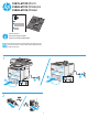
F2A76-67910 (M527) F2A68-67915 (M506n/dn) F2A68-67916 (M506x) Lea esto primero www.hp.com/support/lj506 www.hp.com/support/ljM527MFP CAUTION: Electrostatic sensitive (ESD) parts. Always touch the sheet-metal chassis to provide a static ground before touching an ESD-sensitive part.
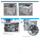
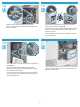
3 4 5 NOTE: M527 fax models only. For all other models, skip this step and go to step 7. Disconnect three connectors (callout 1). Pinch the retainer to release it.
7 6 NOTE: Hard-disk drive (HDD) models only. For all other models, skip this step and go to Step 9. Release the locking connector (callout 1), and then pinch the retainer (callout 2) to release it. Rotate the connector end of the fax PCA out and away from the formatter (callout 1), and then slide it as shown (callout 2) to remove it. 8 9 NOTE: M506 printers and M527dn models only. For all other models, skip this step and go to Step 10 (M506) or Step 11 (M527).
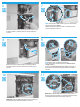
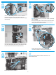
12 13 IMPORTANT: Take note of all empty connectors on the formatter before disconnecting any wire harnesses or flat-flexible cables (FFCs). Some empty connectors might not be visible until other items—like the hard-disk drive—are removed, so pay close attention while removing the formatter and accessories items. M527 only: Pull the DIMM down and away from the holder to remove it. Disconnect all of the connectors and FFCs, remove four screws (callout 1), and then remove the formatter.
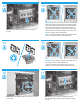
18 19 1 Rotate the bottom edge of the DIMM toward the holder (callout 1), and then make sure that the two locking arms snap into place (callout 2). NOTE: M506 printers and M527dn models only. For all other models, skip this step and go to Step 20. Align the connector on the replacement eMMC (callout 1) with the connector on the formatter, and then push the eMMC onto the formatter to install it. NOTE: The eMMC is keyed and can only be installed in one direction on the formatter.
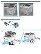
23 22 Make sure that the locking connector (callout 1) latches and that the standoff (callout 2) engages with the slot in the formatter (it might be necessary to pinch the retainer to engage it with the slot). NOTE: M527 fax models only. For all other models, skip this step and go to Step 27. Before proceeding, take note of the location of the slots (callout 1) in the sheet-metal where the fax PCA cradle mounting tab and fax port (callout 2) must be installed.
28 Slide the formatter cover towards the front of the printer to install it.
© Copyright 2015 HP Development Company, L.P. www.hp.