HP 14 Notebook PC Compaq 14 Notebook PC HP 240 G3 Notebook PC HP 245 G3 Notebook PC HP 246 G3 Notebook PC Maintenance and Service Guide
© Copyright 2014 Hewlett-Packard Development Company, L.P. AMD and Radeon are trademarks of Advanced Micro Devices, Inc. Bluetooth is a trademark owned by its proprietor and used by HewlettPackard Company under license. Intel, Celeron, Core, and Pentium are trademarks of Intel Corporation in the U.S. and other countries. Microsoft and Windows are U.S. registered trademarks of the Microsoft group of companies. SD Logo is a trademark of its proprietor.
Safety warning notice WARNING! To reduce the possibility of heat-related injuries or of overheating the device, do not place the device directly on your lap or obstruct the device air vents. Use the device only on a hard, flat surface. Do not allow another hard surface, such as an adjoining optional printer, or a soft surface, such as pillows or rugs or clothing, to block airflow. Also, do not allow the AC adapter to contact the skin or a soft surface, such as pillows or rugs or clothing, during operation.
iv Safety warning notice
Table of contents 1 Product description ....................................................................................................................................... 1 2 External component identification ................................................................................................................. 7 Display ................................................................................................................................................................... 7 Front ..
Service cover ..................................................................................................................................... 55 Memory module ................................................................................................................................ 56 Keyboard ........................................................................................................................................... 57 Top cover .....................................................
Downloading a BIOS update ........................................................................................................... 107 Using HP PC Hardware Diagnostics (UEFI) ........................................................................................................ 107 Downloading HP PC Hardware Diagnostics (UEFI) to a USB device ............................................... 108 8 Specifications ..............................................................................................
Recovering using the recovery media .......................................................................... 121 Changing the computer boot order ........................................................... 121 11 Backup and Recovery in SUSE Linux ........................................................................................................... 123 Backing up your information ...........................................................................................................................
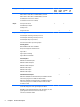
1 Product description Category Description HP/ CPQ14 (Intel) HP/ CPQ14 (AMD) Product name HP 14 Notebook PC √ √ Compaq 14 Notebook PC √ √ HP 240 G3 Notebook PC HP 240/246 G3 √ HP 245 G3 Notebook PC √ HP 246 G3 Notebook PC Processors Intel 5th generation processors: HP 245 G3 √ √ √ Intel Core i5-5200U (2.2 GHz, SC turbo up to 2.7 GHz, 3-MB L3 Cache, 1600MHz) Intel Core i3-5010U (2.1 GHz, 3-MB L3 Cache, 1600MHz) Intel Core i3-5005U (2.
Category Description HP/ CPQ14 (Intel) HP/ CPQ14 (AMD) HP 240/246 G3 HP 245 G3 AMD A4-5000 (1.5GHz, 2MB L2, 1600MHz DDR3L), Quad 15W AMD E2-3800 (1.3GHz, 2MB L2, 1600MHz DDR3L), Quad 15W A4-5050 (Quad-core Processor 1.55GHz) E1-2150 (Dual-core Processor 1.
Category Description HP/ CPQ14 (Intel) HP/ CPQ14 (AMD) HP 240/246 G3 HP 245 G3 Supports LVDS Memory 2 customer-accessible/upgradable memory module slot √ √ Supports dual-channel memory DDR3L-1600-MHz Single Channel Support DDR3L-1333-MHz Single Channel Support (DDR3-1600 downgrade to DDR3-1333) DDR3L-1066-MHz Single Channel Support (DDR3-1600 downgrade to DDR3-1066) Supports up to 16 GB of system RAM in the following configurations: ● 16384-MB total system memory (8192×2) ● 12288-MB total syste
Category Description HP/ CPQ14 (Intel) HP/ CPQ14 (AMD) HP 240/246 G3 HP 245 G3 √ √ √ √ Supports zero power optical drive Audio/video Single digital microphone HD audio Dual speakers HP TrueVision HD webcam (fixed, no tilt with activity LED, 1280×720 by 30 frames per second) Ethernet Integrated 10/100 network interface card (NIC) √ √ √ √ Wireless Integrated wireless local area network (WLAN) options by way of wireless module √ √ √ √ √ √ √ √ √ √ √ √ √ √ √ √ √ √ √ One or
Category Description HP/ CPQ14 (Intel) HP/ CPQ14 (AMD) HP 240/246 G3 HP 245 G3 TouchPad with multi-touch gestures, 2-finger scrolling, and pinchzoom enabled √ √ √ √ √ √ √ √ √ √ √ √ Taps enabled by default Support Win8.1+D212 Modern Trackpad Gestures Support PS/2, profile sensor (reserve for SMBus) Power requirements AC adapters: AC Adapter 65-W Smart nPFC, 3 pin, RC 4.5mm connector - non slim for use in discrete models AC Adapter 45-W Smart nPFC, 3 pin, RC 4.
6 Chapter 1 Product description
2 External component identification Display Component Description (1) WLAN antennas (1 or 2)* (select models only) Send and receive wireless signals to communicate with wireless local area networks (WLANs). (2) Webcam light On: The webcam is in use. (3) Webcam Records video and captures photographs. Some models allow you to video conference and chat online using streaming video.
Front Component Description Memory card reader Reads optional memory cards that store, manage, share, or access information. To insert a card: Hold the card label-side up, with connectors facing the slot, insert the card into the slot, and then push in on the card until it is firmly seated. To remove a card: Pull the card out of the slot. Right side Component Description (1) USB 2.0 ports (2) Connect an optional USB device, such as a keyboard, mouse, external drive, printer, scanner or USB hub.
Left side Component (1) Description Security cable slot Attaches an optional security cable to the computer. NOTE: The security cable is designed to act as a deterrent, but it may not prevent the computer from being mishandled or stolen. (2) Power connector Connects an AC adapter. (3) AC adapter light ● White: The AC adapter is connected and the battery is charged. ● Amber: The AC adapter is connected and the battery is charging. ● Off: The computer is using battery power.
Component Description WARNING! To reduce the risk of personal injury, adjust the volume before putting on headphones, earbuds, or a headset. For additional safety information, refer to the Regulatory, Safety, and Environmental Notices. To access this guide in Windows 8, from the Start screen, type support, and then select the HP Support Assistant app. NOTE: When a device is connected to the jack, the computer speakers are disabled.
Top TouchPad Component (1) Description TouchPad zone Moves the on-screen pointer and selects or activates items on the screen. NOTE: The TouchPad also supports edge-swipe gestures. (2) Left TouchPad button Functions like the left button on an external mouse. (3) Right TouchPad button Functions like the right button on an external mouse.
Lights Component (1) Description Power light ● On: The computer is on. ● Blinking: The computer is in the Sleep state, a powersaving state. The computer shuts off power to the display and other unneeded components. ● Off: The computer is off or in Hibernation. Hibernation is a power-saving state that uses the least amount of power. (2) Caps lock light On: Caps lock is on, which switches the keys to all capital letters. (3) Mute light ● Amber: Computer sound is off.
Button Component Description Power button ● When the computer is off, press the button to turn on the computer. ● When the computer is on, press the button briefly to initiate Sleep. ● When the computer is in the Sleep state, press the button briefly to exit Sleep. ● When the computer is in Hibernation, press the button briefly to exit Hibernation. CAUTION: Pressing and holding down the power button will result in the loss of unsaved information.
Keys Component Description (1) esc key Displays system information when pressed in combination with the fn key. (2) fn key Executes frequently used system functions when pressed in combination with the spacebar or the esc key. (3) Windows key Windows 8: Returns you to the Start screen from an open app or the Windows desktop. NOTE: Pressing the Windows key again will return you to the previous screen. Windows 7: Displays the Windows Start menu.
Bottom Component Description (1) Battery lock and unlock latch Locks and unlocks the battery in the battery bay. (2) Battery bay Holds the battery. (3) Vent Enable airflow to cool internal components. NOTE: The computer fan starts up automatically to cool internal components and prevent overheating. It is normal for the internal fan to cycle on and off during routine operation. (4) Battery release latch Releases the battery. (5) Speaker openings (4) Produce sound.
Labels The labels affixed to the computer provide information you may need when you troubleshoot system problems or travel internationally with the computer. IMPORTANT: All labels described in this section will be located in one of 2 places depending on your computer model: Affixed to the bottom of the computer, or located in the battery bay. ● Service label—Provides important information to identify your computer.
Component (4) Model number (select models only) (5) Revision number ● Regulatory label(s)—Provide(s) regulatory information about the computer. ● Wireless certification label(s)—Provide(s) information about optional wireless devices and the approval markings for the countries or regions in which the devices have been approved for use.
18 Chapter 2 External component identification
3 Illustrated parts catalog Computer major components NOTE: HP continually improves and changes product parts. For complete and current information on supported parts for your computer, go to http://partsurfer.hp.com, select your country or region, and then follow the on-screen instructions.
Item Component (1) Display assembly (35.6-cm [14.0-in] HD, anti-glare, WLED) NOTE: (2) (3) Spare part number For display assembly spare part information, see Display assembly subcomponents on page 27.
Item Component Spare part number ● 773067-001 Top cover (4) Power connector cable 760104-001 (5) Touchpad button board (includes cables) 757609-001 (6) Fan 753894-001 (7) RTC battery 759981-001 (8) Power button board (includes cable) 757607-001 (9a) For use in models with Intel processors and discrete graphics 757602-001 For use in models with an Intel Core i3-3217U processor and discrete graphics 766502-001 For use in models with AMD processors and discrete graphics 766567-001 F
Item Component Spare part number Non-touch screen models with an Intel Pentium N3540 processor and UMA graphics 788003-xxx Touch screen models with an Intel Pentium N3540 processor and UMA graphics 788208-xxx Non-touch screen models with an Intel Celeron N2920 processor and UMA graphics 790213-xxx Non-touch screen models with an Intel Celeron N2840 processor and UMA graphics 788004-xxx Non-touch screen models with an Intel Celeron N2820 processor and UMA graphics 790212-xxx Non-touch screen mod
Item Component Spare part number Non-touch screen models with an Intel Core i3-3217U processor and UMA graphics 766645-xxx Non-touch screen, GLAN models with an Intel Core i3-3217U processor and UMA graphics 795137-xxx Touch screen models with an Intel Core i3-3217U processor and UMA graphics 776462-xxx Non-touch screen models with an Intel Pentium N3530 processor and UMA graphics 775629-xxx Non-touch screen models with an Intel Celeron N2830 processor and UMA graphics 775632-xxx Non-touch scre
Item Component Spare part number AMD E1-6010 processor with 1 GB of discrete graphics memory without a touch screen ● Without Windows 8 776931-001 ● Windows 8 Standard 776931-501 AMD A6-5200 processor with UMA graphics without a touch screen ● Without Windows 8 762422-001 ● Windows 8 Standard 762422-501 ● Windows 8 Professional 762422-601 AMD A6-5200 processor with UMA graphics memory and a touch screen ● Without Windows 8 762423-001 ● Windows 8 Standard 762423-501 AMD A4-5050 proces
Item Component Spare part number ● Without Windows 8 762424-001 ● Windows 8 Standard 762424-501 ● Windows 8 Professional 762424-601 AMD E1-2100 processor with 2 GB of discrete graphics memory without a touch screen ● Without Windows 8 762429-001 ● Windows 8 Standard 762429-501 HP 245 G3 models: AMD A4-5000 processor and 1 GB of discrete graphics without a touch screen: ● Without Windows 8 766011-001 ● Windows 8 Standard 766011-501 ● Windows 8 Professional 766011-601 AMD A6-6310 pr
Item (16) Component Spare part number 500-GB, 5400-rpm, 7 mm (HP 240/246 G3 models only) 683802-005 Battery: 4-cell, 41-Whr, 2.8-Ah Li-ion battery 740715-001 3-cell, 31-Whr, 2.
Display assembly subcomponents Item Component (1) Display bezel (includes Mylar screw covers): (2) (3) Spare part number For use with HP 14 models 757599-001 For use with HP 240/246 G3 models 766009-001 For use with HP 245 G3 models 766900-001 For use with Compaq 14 models 757600-001 Webcam/microphone module HD 757614-001 VGA 781623-001 Raw display panel (35.6-cm [14.
Item (4) (5) (6) (7) Component Spare part number Touch screen, HP 14 models 760106-001 Touch screen, HP 245 G3 models 778156-001 Hinges (left and right) Non-touch screen models 757605-001 Touch screen models 766585-001 Display cable (includes display panel cable and webcam/microphone cable) Non-touch screen models 757601-001 Touch screen models 757597-001 Antennas (includes wireless antenna cables and transceivers) Non-touch screen models 757596-001 Touch screen models 766589-001 Disp
Mass storage devices Item Component (1) Optical drive (DVD+/-RW Double-Layer SuperMulti) (2) Spare part number For use in HP 14 and Compaq 14 models 757606-001 For use in HP 240/246 and 245 G3 models 766899-001 Hard drive, SATA; does not include bracket): 1-GB, 5400-rpm 778192-005 750-GB, 5400-rpm (HP 14 and Compaq 14 models only) 778190-005 750-GB, 5400-rpm (HP 240/246 and HP 245 G3 models only) 634250-005 500-GB, 5400-rpm (HP 14 and Compaq 14 models only) 778188-005 500-GB, 5400-rpm (HP
Component Spare part number For use in Taiwan 490371-AB1 For use in Thailand 490371-201 For use in the United Kingdom and Singapore 490371-031 Power cord (3-pin, black, 1.
Spare part number Description 490371-AB1 Power cord for use in Taiwan (3-pin, black, 1.83-m) 490371-AD1 Power cord for use in South Africa (3-pin, black, 1.83-m) 490371-AR1 Power cord for use in South Korea (3-pin, black, 1.83-m) 490371-BB1 Power cord for use in Israel (3-pin, black, 1.83-m) 490371-D01 Power cord for use in Argentina (3-pin, black, 1.83-m) 490371-D61 Power cord for use in India (3-pin, black, 1.
32 Spare part number Description 755530-AA1 Power cord for use in the People’s Republic of China (3-pin, black, 1.00-m) 755530-AB1 Power cord for use in Taiwan (3-pin, black, 1.00-m) 755530-AD1 Power cord for use in South Korea (3-pin, black, 1.00-m) 755530-D01 Power cord for use in Argentina (3-pin, black, 1.00-m) 755530-D61 Power cord for use in India (3-pin, black, 1.
Spare part number Description 755834-601 System board for use in non-touch screen models with an Intel Core i5-4210U processor and 2 GB of discrete graphics in HP 14 and Compaq 14 models with Windows 8 Professional 755835-001 System board for use in non-touch screen HP 14, Compaq 14, and HP 240/246 G3 models without Windows 8 and equipped with an Intel Core i5-4210U processor and UMA graphics (includes replacement thermal materials) 755835-501 System board for use in non-touch screen HP 14, Compaq 14
34 Spare part number Description 757608-001 USB board (includes cable) 757609-001 TouchPad button board (includes cables) 757610-001 System board for use in touch screen models with an Intel Core i5-4210U processor and 2 GB of discrete graphics in HP 14 and Compaq 14 models without Windows 8 757610-501 System board for use in touch screen models with an Intel Core i5-4210U processor and 2 GB of discrete graphics in HP 14 and Compaq 14 models with Windows 8 Standard 757610-601 System board for us
Spare part number Description 757922-DB1 Keyboard for use in French Canada 757922-DH1 Keyboard for use in Denmark, Finland, and Norway 757922-FL1 Keyboard for use in the Czech Republic and Slovakia 758603-001 Display enclosure for use in black HP 14 models 758604-001 Display enclosure for use in white HP 14 models 758605-001 Display enclosure for use in red HP 14 models 758606-001 Display enclosure for use in blue HP 14 models 758607-001 Display enclosure for use in gray Compaq 14 non-touch
36 Spare part number Description 760106-001 Raw display panel for use in HP 14 models, touch screen 760246-001 Display enclosure for use in silver HP 14 and Compaq 14 models with a touch screen 760247-001 Top cover for use in silver models (includes touchpad) 762239-001 System board for use in touch screen models with an Intel Core i3-3217U processor and UMA graphics in HP 14 and Compaq 14 models without Windows 8 762239-501 System board for use in touch screen models with an Intel Core i3-3217U
Spare part number Description 762426-501 System board for use in models with an AMD E1-2150 processor, with UMA graphics, without a touch screen, with Windows 8 Standard 762427-001 System board for use in models with an AMD A4-5000 processor, with UMA graphics, without a touch screen, without Windows 8 762427-501 System board for use in models with an AMD A4-5000 processor, with UMA graphics, without a touch screen, with Windows 8 Standard 762427-601 System board for use in models with an AMD A4-50
38 Spare part number Description 764172-001 System board for use in models with an AMD A4-6210 processor, with UMA graphics, without a touch screen, without Windows 8 764172-501 System board for use in models with an AMD A4-6210 processor, with UMA graphics, without a touch screen, with Windows 8 Standard 764173-001 System board for use in models with an AMD E2-6110 processor, with UMA graphics, without a touch screen, without Windows 8 764173-501 System board for use in models with an AMD E2-6110
Spare part number Description 766503-001 Heat sink for use in models with an Intel Core 3217U processor and UMA graphics 766504-001 Heat sink for use in models with Intel Pentium and Celeron processors and UMA graphics 766505-001 Rubber feet for use on HP 14 and Compaq 14 models 766567-001 Heat sink assembly for use in models with AMD processors and discrete graphics (includes replacement thermal materials) 766568-001 Heat sink assembly for use in models with AMD processors and UMA graphics (incl
40 Spare part number Description 775629-001 System board for use in non-touch screen models with an Intel Pentium N3520 processor and UMA graphics in HP 240 G3 models without Windows 8 775629-501 System board for use in non-touch screen models with an Intel Pentium N3520 processor and UMA graphics in HP 240 G3 models with Windows 8 Standard 775629-601 System board for use in non-touch screen models with an Intel Pentium N3520 processor and UMA graphics in HP 240 G3 models with Windows 8 Professional
Spare part number Description 778116-601 System board for use in non-touch screen models with an Intel Core i5-5200U processor and UMA graphics in HP 14, Compaq 14, and HP 240 G3 models with Windows 8 Professional 778156-001 Raw display panel for use in HP 245 G3 models, touch screen 778188-005 750-GB, 5400-rpm hard drive (HP 14 and Compaq 14 models only; does not include cable or bracket) 778190-005 500-GB, 5400-rpm hard drive (HP 14 and Compaq 14 models only; does not include cable or bracket) 7
42 Spare part number Description 788208-001 System board for use in touch screen models with an Intel Pentium N3540 processor and UMA graphics in HP 14, Compaq 14, and HP 240 G3 models without Windows 8 788208-501 System board for use in touch screen models with an Intel Pentium N3540 processor and UMA graphics in HP 14, Compaq 14, and HP 240 G3 models with Windows 8 Standard 788208-601 System board for use in touch screen models with an Intel Pentium N3540 processor and UMA graphics in HP 14, Compa
Spare part number Description 791095-501 System board for use in non-touch screen models with an Intel Core i3-5005U processor and 2 GB of discrete graphics in HP 14, Compaq 14, and HP 240/246 G3 models with Windows 8 Standard 791095-601 System board for use in non-touch screen models with an Intel Core i3-5005U processor and 2 GB of discrete graphics in HP 14, Compaq 14, and HP 240/246 G3 models with Windows 8 Professional 791096-001 System board for use in non-touch screen models with an Intel Core
44 Spare part number Description 801855-501 System board for use in non-touch screen models with an Intel Core i3-5010U processor and UMA graphics in HP 14, Compaq 14, and HP 240 G3 models with Windows 8 Standard 801855-601 System board for use in non-touch screen models with an Intel Core i3-5010U processor and UMA graphics in HP 14, Compaq 14, and HP 240 G3 models with Windows 8 Professional 801856-001 System board for use in non-touch screen models with an Intel Core i3-5010U processor and 1 GB o
4 Removal and replacement procedures Preliminary replacement requirements Tools required You will need the following tools to complete the removal and replacement procedures: ● Flat-bladed screwdriver ● Magnetic screwdriver ● Phillips P0 and P1 screwdrivers Service considerations The following sections include some of the considerations that you must keep in mind during disassembly and assembly procedures.
Drive handling CAUTION: Drives are fragile components that must be handled with care. To prevent damage to the computer, damage to a drive, or loss of information, observe these precautions: Before removing or inserting a hard drive, shut down the computer. If you are unsure whether the computer is off or in Hibernation, turn the computer on, and then shut it down through the operating system. Before handling a drive, be sure that you are discharged of static electricity.
Typical electrostatic voltage levels Relative humidity Event 10% 40% 55% Walking across carpet 35,000 V 15,000 V 7,500 V Walking across vinyl floor 12,000 V 5,000 V 3,000 V Motions of bench worker 6,000 V 800 V 400 V Removing DIPS from plastic tube 2,000 V 700 V 400 V Removing DIPS from vinyl tray 11,500 V 4,000 V 2,000 V Removing DIPS from Styrofoam 14,500 V 5,000 V 3,500 V Removing bubble pack from PCB 26,500 V 20,000 V 7,000 V Packing PCBs in foam-lined box 21,000 V 11,0
● Avoid contact with pins, leads, or circuitry. ● Turn off power and input signals before inserting or removing connectors or test equipment. Equipment guidelines Grounding equipment must include either a wrist strap or a foot strap at a grounded workstation. ● When seated, wear a wrist strap connected to a grounded system. Wrist straps are flexible straps with a minimum of one megohm ±10% resistance in the ground cords. To provide proper ground, wear a strap snugly against the skin at all times.
Component replacement procedures This chapter provides removal and replacement procedures. Make special note of each screw's size and location during removal and replacement. NOTE: HP continually improves and changes product parts. For complete and current information on supported parts for your computer, go to http://partsurfer.hp.com, select your country or region, and then follow the on-screen instructions. Battery Description Spare part number 4-cell, 41-Whr, 2.
Display subcomponents (bezel, webcam, panel) This section describes removing display subcomponents that do not require that you remove the entire display assembly from the computer. You can remove the display bezel, webcam/microphone module, and display panel while the display assembly is still attached to the computer. To remove the remaining display subcomponents, you must remove the entire display assembly from the computer.
4. Remove the display bezel. 5. To remove the webcam/microphone module: 6. a. Position the display assembly with the top edge toward you. b. Lift to disengage the adhesive that secures the webcam/microphone module to the display, and then lift the module enough to access the cable connection on the module (1). c. Disconnect the cable (2) from the module. To remove the display panel: a. Remove the four Phillips PM2.0×3.0 screws that secure the display panel to the enclosure.
b. Rotate the display panel onto the keyboard to gain access to the display cable connection on the back of the panel (1). c. On the back of the display panel, release the adhesive strip (2) that secures the display panel cable to the display panel, and then disconnect the cable (3). Reverse this procedure to reassemble and install the display bezel, webcam/microphone module, and display panel.
Optical drive Description Spare part number DVD+/-RW Double-Layer SuperMulti Drive for use in HP 14 and Compaq 14 models 757606-001 DVD+/-RW Double-Layer SuperMulti Drive for use in HP 240/246 and HP 245 G3 models 766899-001 Before removing the optical drive, follow these steps: 1. Shut down the computer. If you are unsure whether the computer is off or in Hibernation, turn the computer on, and then shut it down through the operating system. 2.
5. Remove the optical drive bracket (2). Reverse this procedure to reassemble and install the optical drive.
Service cover Description Spare part number Service cover 758616-001 Before removing the service cover, follow these steps: 1. Shut down the computer. If you are unsure whether the computer is off or in Hibernation, turn the computer on, and then shut it down through the operating system. 2. Disconnect all external devices connected to the computer. 3. Disconnect the power from the computer by first unplugging the power cord from the AC outlet and then unplugging the AC adapter from the computer.
Memory module Description Spare part number 8-GB (PC3L, 12800, 1600-MHz) 693374-001 4-GB (PC3L, 12800, 1600-MHz) 691740-001 2-GB (PC3L, 12800, 1600-MHz) 691739-001 Before removing a memory module, follow these steps: 1. Shut down the computer. If you are unsure whether the computer is off or in Hibernation, turn the computer on, and then shut it down through the operating system. 2. Disconnect all external devices connected to the computer. 3.
Keyboard Description Spare part number Keyboard for use in the United States 757922-001 Keyboard for use in the United Kingdom 757922-031 Keyboard for use in France 757922-051 Keyboard for use in Spain 757922-071 Keyboard for use in Portugal 757922-131 Keyboard for use in Turkey 757922-141 Keyboard for use in Latin America 757922-161 Keyboard for use in Saudi Arabia 757922-171 Keyboard for use in Brazil 757922-201 Keyboard for use in Russia 757922-251 Keyboard for use in Thailand 7579
2. Remove the two Phillips PM2.5×5.0 screws that secure the keyboard to the computer. 3. Position the computer upright with the front toward you. 4. Lift to rotate up the top of the keyboard (1), and then lift the keyboard (2) to disengage it from the computer. NOTE: 58 You may need to use a flat tool to pry up under the top of the keyboard to disengage it.
5. Rotate the keyboard over onto the palm rest (1), and the lift the ZIF connector (2) and disconnect the keyboard cable from the system board (3). Reverse this procedure to install the keyboard.
Top cover NOTE: The top cover spare part kit includes the TouchPad.
2. Remove the nine Phillips PM2.5×8.0 screws that secure the top cover to the computer.
3. Remove the rear covers from the computer. The rear covers are included in the base enclosure kit, spare part number 757598-001 for HP 14 and Compaq 14 models, 766898-001 for HP 240/246 and HP 245 G3 models. 62 4. Remove the two Phillips broadhead PM2.0×2.0 screws from the optical drive bay that secure the top cover to the computer. 5. Position the computer upright with the front toward you.
6. Disconnect the power button board cable (1) and the touchpad button board cable (2). 7. Remove the three Phillips PM2.5×4.0 screws that secure the top cover to the computer. 8. Lift the rear edge of the top cover (1) until it disengage from the base enclosure. NOTE: The top cover may be very tightly secured to the computer.
9. Remove the top cover (2). Reverse this procedure to install the top cover.
Power button board Description Spare part number Power button board (includes cable) 757607-001 Before removing the power button board, follow these steps: 1. Shut down the computer. If you are unsure whether the computer is off or in Hibernation, turn the computer on, and then shut it down through the operating system. 2. Disconnect all external devices connected to the computer. 3.
TouchPad button board Description Spare part number TouchPad button board (includes cables) 757609-001 Before removing the TouchPad button board, follow these steps: 1. Shut down the computer. If you are unsure whether the computer is off or in Hibernation, turn the computer on, and then shut it down through the operating system. 2. Disconnect all external devices connected to the computer. 3.
USB board Description Spare part number USB board (includes cable) 757608-001 Before removing the USB board, follow these steps: 1. Shut down the computer. If you are unsure whether the computer is off or in Hibernation, turn the computer on, and then shut it down through the operating system. 2. Disconnect all external devices connected to the computer. 3.
Hard drive NOTE: The hard drive spare part kit does not include the hard drive bracket.
2. Remove the two Phillips PM2.5×3.0 screws (1) that secure the hard drive to the computer. 3. Slide the hard drive to disengage it from the connector (2). 4. Lift the hard drive from the computer (3). 5. To remove the hard drive bracket, remove the two Phillips PM3.0×4.0 screws (1) that secure the bracket to the hard drive.
6. Remove the hard drive bracket from the hard drive (2). Reverse this procedure to reassemble and install the hard drive.
WLAN module Description Spare part number Atheros AR9485 802.11b/g/n 1x1 WiFi Adapter 675794-005 Ralink RT3290LE 802.11bgn 1x1 Wi-Fi and Bluetooth 4.0 Combo Adapter 690020-005 Atheros AR9565 802.11bgn 1x1 WiFi + BT4.0 combo Adapter for use in Brazil 712639-205 Realtek RTL8188EE 802.11bgn Wi-Fi Adapter 709848-005 Realtek RT8723BE 802.11bgn 1x1 Wi-Fi + BT4.
3. Remove the WLAN module by pulling the module away from the connector (3). NOTE: If the WLAN antennas are not connected to the terminals on the WLAN module, the protective sleeves must be installed on the antenna connectors, as shown in the following illustration. Reverse this procedure to install the WLAN module.
Power connector cable Description Spare part number Power connector cable 760104-001 Before removing the power connector cable, follow these steps: 1. Shut down the computer. If you are unsure whether the computer is off or in Hibernation, turn the computer on, and then shut it down through the operating system. 2. Disconnect all external devices connected to the computer. 3.
Fan Description Spare part number Fan 753894-001 NOTE: To properly ventilate the computer, allow at least 7.6 cm (3.0 in) of clearance on the left side of the computer. The computer uses an electric fan for ventilation. The fan is controlled by a temperature sensor and is designed to turn on automatically when high temperature conditions exist.
4. Remove the fan from the computer (3). Reverse this procedure to install the fan.
Display assembly This section describes removing the display assembly in its entirety and disassembling all the display subcomponents. If you only need to remove the display bezel, webcam/microphone module, or display panel, you do not need to remove the entire display assembly from the computer. See Display subcomponents (bezel, webcam, panel) on page 50 for more information about removing the display subcomponents that do not require that you remove the entire display assembly from the computer.
Description Spare part number Webcam/microphone module, HD 757614-001 Webcam/microphone module, VGA 781623-001 Before removing the display assembly, follow these steps: 1. Shut down the computer. If you are unsure whether the computer is off or in Hibernation, turn the computer on, and then shut it down through the operating system. 2. Disconnect all external devices connected to the computer. 3.
3. Remove the six Phillips PM2.5×4.0 screws (1) (three from each hinge) that secure the display assembly to the computer. 4. Remove the display assembly (2). If it is necessary to replace any of the display assembly subcomponents: 1. 78 To remove the display bezel: a. Remove the two Mylar covers (1) and two Phillips PM2.0×3.0 screws (2) that secure the bezel to the display. b.
c. Remove the display bezel. NOTE: In this procedure, the display will NOT be connected to the computer, as shown in the following image. 2. 3. To remove the webcam/microphone module: a. Position the display assembly with the top edge toward you. b. Disconnect the cable (1) from the module. c. Remove the webcam/microphone module (2). (The module is attached to the display enclosure with double-sided tape.) To remove the display panel: a. Remove the four Phillips PM2.0×3.
NOTE: In this procedure, the display will NOT be connected to the computer, as shown in the following image. b. Rotate the display panel onto the keyboard to gain access to the display cable connection on the back of the panel (1). c. On the back of the display panel, release the adhesive strip (2) that secures the display panel cable to the display panel, and then disconnect the cable (3). NOTE: In this procedure, the display will NOT be connected to the computer, as shown in the following image. 4.
5. a. Remove the six broadhead Phillips PM2.5×2.5 screws (1) and the two Phillips PM2.0×2.5 screws (2) that secure the display hinges to the display enclosure. b. Remove the display hinges (3). To remove the wireless antenna cables and transceivers, release the wireless antenna cables from the clips built into the display enclosure (1), and then lift the antenna cables from the display enclosure (2). NOTE: The number of antenna cables may vary.
6. To remove the display/webcam cable, remove the cable from the clips built into the display enclosure (1), and then remove the cable from the display enclosure (2). NOTE: If replacing the display enclosure, be sure that the subcomponents (including the webcam/ microphone module, the antenna receivers, and all associated cables and hardware) are transferred to the new enclosure. Reverse this procedure to reassemble and install the display assembly.
System board NOTE: The system board spare part kit includes replacement thermal materials. All Intel system boards use the following part numbers: xxxxxx-001: Without the Windows operating system xxxxxx-501: Windows 8.1 Standard xxxxxx-601: Windows 8.1 Professional Description Spare part number HP 14, Compaq 14, and HP 240/246 G3 models with Intel processors: NOTE: HP 246 G3 models offer only discrete graphics.
Description Spare part number Touch screen models with an Intel Core i5-4210U processor and 2 GB of discrete graphics 757610-xxx Non-touch screen models with an Intel Core i5-4210U processor and 1 GB of discrete graphics 788210-xxx Touch screen models with an Intel Core i5-4030U processor and 2 GB of discrete graphics 784981-xxx Touch screen models with an Intel Core i3-4010U processor and 2 GB of discrete graphics 758614-xxx Non-touch screen models with an Intel Core i3-4010U processor and 2 GB o
Description Spare part number ● Without Windows 8 764171-001 ● Windows 8 Standard 764171-501 AMD A8-6410 processor with 2 GB of discrete graphics memory without a touch screen ● Without Windows 8 764176-001 ● Windows 8 Standard 764176-501 AMD A4-6210 processor with UMA graphics without a touch screen ● Without Windows 8 764172-001 ● Windows 8 Standard 764172-501 AMD A4-6210 processor with 2 GB of discrete graphics memory without a touch screen ● Without Windows 8 764171-001 ● Windows
Description Spare part number ● Without Windows 8 762425-001 ● Windows 8 Standard 762425-501 AMD A4-5050 processor with 2 GB of discrete graphics memory without a touch screen ● Without Windows 8 762430-001 ● Windows 8 Standard 762430-501 AMD A4-5050 processor with 1 GB of discrete graphics memory without a touch screen ● Without Windows 8 762428-001 ● Windows 8 Standard 762428-501 AMD A4-5000 processor with UMA graphics without a touch screen ● Without Windows 8 762427-001 ● Windows
Description Spare part number AMD A6-6310 processor and UMA graphics memory with a touch screen: ● Without Windows 8 793101-001 ● Windows 8 Standard 793101-501 ● Windows 8 Professional 793101-601 Before removing the system board, follow these steps: 1. Shut down the computer. If you are unsure whether the computer is off or in Hibernation, turn the computer on, and then shut it down through the operating system. 2. Disconnect all external devices connected to the computer. 3.
2. Remove the three Phillips PM2.5×4.0 screws (1) that secure the system board to the computer. 3. Lift the right side of the system board (2), and then pull the board away from the computer to remove it. Reverse this procedure to install the system board.
Speakers Description Spare part number Speakers (includes left and right speakers and cable) 757612-001 Before removing the speakers, follow these steps: 1. Shut down the computer. If you are unsure whether the computer is off or in Hibernation, turn the computer on, and then shut it down through the operating system. 2. Disconnect all external devices connected to the computer. 3.
3. Lift the speakers from the base enclosure (2). NOTE: Note the rubber gaskets around each screw. When installing the speakers, make sure the gaskets are installed correctly. Reverse this procedure to install the speakers.
Heat sink assembly NOTE: The heat sink assembly spare part kit includes replacement thermal materials.
3. Remove the heat sink assembly (2) from the system board.
The thermal material must be thoroughly cleaned from the surfaces of the heat sink and the system board components each time the heat sink is removed. Replacement thermal material is included with the heat sink, processor, and system board spare part kits. The following illustrations show replacement thermal material locations. ● Discrete graphics: Thermal paste is used on the processor and associated heat sink area (1)(2), as well as the graphics chip and associated heat sink area (3)(4).
RTC battery Description Spare part number RTC battery 759981-001 Before removing the RTC battery, follow these steps: 1. Shut down the computer. If you are unsure whether the computer is off or in Hibernation, turn the computer on, and then shut it down through the operating system. 2. Disconnect all external devices connected to the computer. 3. Disconnect the power from the computer by first unplugging the power cord from the AC outlet and then unplugging the AC adapter from the computer. 4.
2. Using a thin tool or screwdriver, disengage the battery from the socket (1), and then remove the battery (2). Reverse this procedure to install the RTC battery.
96 Chapter 4 Removal and replacement procedures
5 Using Setup Utility (BIOS) and HP PC Hardware Diagnostics (UEFI) in Windows 8 Setup Utility, or Basic Input/Output System (BIOS), controls communication between all the input and output devices on the system (such as disk drives, display, keyboard, mouse, and printer). Setup Utility (BIOS) includes settings for the types of devices installed, the startup sequence of the computer, and the amount of system and extended memory.
Downloading a BIOS update CAUTION: To reduce the risk of damage to the computer or an unsuccessful installation, download and install a BIOS update only when the computer is connected to reliable external power using the AC adapter. Do not download or install a BIOS update while the computer is running on battery power, docked in an optional docking device, or connected to an optional power source.
the operating system so that it can isolate hardware failures from issues that are caused by the operating system or other software components. To start HP PC Hardware Diagnostics UEFI: 1. Turn on or restart the computer, quickly press esc, and then press f2. The BIOS searches three places for the diagnostic tools, in the following order: a.
100 Chapter 5 Using Setup Utility (BIOS) and HP PC Hardware Diagnostics (UEFI) in Windows 8
6 Using Setup Utility (BIOS) and System Diagnostics in Windows 7 Setup Utility, or Basic Input/Output System (BIOS), controls communication between all the input and output devices on the system (such as disk drives, display, keyboard, mouse, and printer). Setup Utility (BIOS) includes settings for the types of devices installed, the startup sequence of the computer, and the amount of system and extended memory. Starting Setup Utility (BIOS) To start Setup Utility (BIOS), follow these steps: 1.
Downloading a BIOS update CAUTION: To reduce the risk of damage to the computer or an unsuccessful installation, download and install a BIOS update only when the computer is connected to reliable external power using the AC adapter. Do not download or install a BIOS update while the computer is running on battery power, docked in an optional docking device, or connected to an optional power source.
To start HP PC Hardware Diagnostics UEFI: 1. Turn on or restart the computer, quickly press esc, and then press f2. The BIOS searches three places for the diagnostic tools, in the following order: a. Connected USB drive NOTE: To download the HP PC Hardware Diagnostics (UEFI) tool to a USB drive, see Downloading HP PC Hardware Diagnostics (UEFI) to a USB device on page 103. 2. b. Hard drive c.
104 Chapter 6 Using Setup Utility (BIOS) and System Diagnostics in Windows 7
7 Computer Setup (BIOS) and HP PC Hardware Diagnostics (UEFI) in SUSE Linux Computer Setup, or Basic Input/Output System (BIOS), controls communication between all the input and output devices on the system (such as disk drives, display, keyboard, mouse, and printer). Computer Setup includes settings for the types of peripherals installed, the startup sequence of the computer, and the amount of system and extended memory. NOTE: Use extreme care when making changes in Computer Setup.
Use the tab key and the arrow keys to select File > Ignore Changes and Exit, and then press enter. – or – ● To save your changes and exit Computer Setup menus, click the Save icon in the lower-left corner of the screen, and then follow the on-screen instructions. – or – Use the tab key and the arrow keys to select File > Save Changes and Exit, and then press enter. Your changes go into effect when the computer restarts.
Use the tab key and the arrow keys to select File > Ignore Changes and Exit, and then press enter. NOTE: You can also determine the BIOS version by turning on or restarting the computer, pressing the esc key while the “Press the ESC key for Startup Menu” message is displayed at the bottom of the screen, and then pressing the f1 key. Follow the on-screen instructions to exit this screen.
NOTE: To download the HP PC Hardware Diagnostics (UEFI) tool to a USB drive, see Downloading HP PC Hardware Diagnostics (UEFI) to a USB device on page 108. b. 2. BIOS When the diagnostic tool opens, use the keyboard arrow keys to select the type of diagnostic test you want to run, and then follow the on-screen instructions. NOTE: If you need to stop a diagnostic test, press esc.
8 Specifications Computer specifications Metric U.S. Depth 244 mm 9.61 in Width 345 mm 13.58 in Height 25.3 mm 1.00 in Weight (with 3 cell battery) 1910 g 4.21 lb Dimensions (touch models) Input power Operating voltage and current 18.5 V dc @ 3.5 A or 19.5 V dc @ 3.33 A – 65 W 19 V dc @ 4.74 A or 19.5 V dc @ 4.
35.6-cm (14.0-in) display specifications Metric U.S. Height 17.6 cm 6.93 in Width 31.2 cm 12.28 in Diagonal 35.7 cm 14.06 in Number of colors Up to 16.8 million Contrast ratio 200:1 (typical) Brightness 200 nits (typical) Dimensions Pixel resolution Pitch 0.197 × 0.197 mm Format 1366 × 768 Configuration RGB vertical stripe Backlight LED Character display 80 × 25 Total power consumption 2.
Hard drive specifications 1-TB* 750-GB* 500-GB* (9.5 mm) (7.0 mm) Dimensions Height 9.5 mm 9.5 mm 7.0 mm or 9.5 mm Length 100.4 mm 100.4 mm 100.6 mm Width 69.9 mm 69.9 mm 70.1 mm Weight 115.0 g 115.0 g 92.0 g Interface type SATA SATA SATA Synchronous (maximum) 300 MB/sec 300 MB/sec 300 MB/sec Security ATA security ATA security ATA security Single track 1.4 ms 1.
DVD±RW SuperMulti DL Drive specifications Applicable disc Center hole diameter Read: Write: CD-DA, CD+(E)G, CD-MIDI, CD-TEXT, CD-ROM, CDROM XA, MIXED MODE CD, CD-I, CD-I Bridge (PhotoCD, Video CD), Multisession CD (Photo-CD, CDEXTRA, Portfolio, CD-R, CD-RW), CD-R, CD-RW, DVD-ROM (DVD-5, DVD-9, DVD-10, DVD-18), DVDR, DVD-RW, DVD+R, DVD+RW, DVD-RAM CD-R and CD-RW DVD+R, DVD+RW, DVD-R, DVD-RW, DVD-RAM 1.5 cm (0.59 in) Disc diameter Standard disc 12 cm (4.72 in) Mini disc 8 cm (3.
9 Backing up, restoring, and recovering in Windows 8 This chapter provides information about the following processes: ● Creating recovery media and backups ● Restoring and recovering your system Creating recovery media and backups 1. After you successfully set up the computer, create HP Recovery media. This step creates a backup of the HP Recovery partition on the computer.
● If your computer does not include an integrated optical drive with DVD writer capability, but you would like to create DVD recovery media, you can use an external optical drive (purchased separately) to create recovery discs, or you can obtain recovery discs for your computer from support. See the Worldwide Telephone Numbers booklet included with the computer. You can also find contact information from the HP website. Go to http://www.hp.
● If you have replaced the hard drive, you can use the Factory Reset option of HP Recovery media to restore the factory image to the replacement drive. For more information, see Recovering using HP Recovery Manager on page 115. ● If you wish to remove the recovery partition to reclaim hard drive space, HP Recovery Manager offers the Remove Recovery Partition option. For more information, see Removing the HP Recovery partition on page 116.
1. Press f11 while the computer boots. – or – Press and hold f11 as you press the power button. 2. Choose your keyboard layout. 3. Select Troubleshoot from the boot options menu. 4. Select Recovery Manager, and then follow the on-screen instructions. Using HP Recovery media to recover You can use HP Recovery media to recover the original system. This method can be used if your system does not have an HP Recovery partition or if the hard drive is not working properly. 1.
10 Backing up, restoring, and recovering in Windows 7 Your computer includes tools provided by the operating system and HP to help you safeguard your information and retrieve it if ever needed. Creating backups 1. Use HP Recovery Manager to create recovery media immediately after you set up the working computer. 2. As you add hardware and software programs, create system restore points. 3.
Creating the recovery media 1. Select Start and type recovery in the search field. Select Recovery Manager from the list. Allow the action to continue, if prompted. 2. Click Recovery Media Creation. 3. Follow the on-screen instructions to continue. To recover, see Recovering the original system using HP Recovery Manager on page 120. Creating system restore points A system restore point is a snapshot of certain hard drive contents saved by Windows System Restore at a specific time.
Tips for a successful backup ● Number backup discs before inserting them into the optical drive. ● Store personal files in the Documents, Music, Pictures, and Videos libraries, and back up these folders periodically. ● Save customized settings in a window, toolbar, or menu bar by taking a screen shot of your settings. The screen shot can be a time-saver if you have to re-enter your preferences. To create a screen shot: 1. Display the screen you want to save. 2.
Restore and recovery Restoring to a previous system restore point Sometimes installing a software program causes your computer or Windows to behave unpredictably. Usually uninstalling the software fixes the problems. If uninstalling does not fix the problems, you can restore the computer to a previous system restore point (created at an earlier date and time). To restore to a previous system restore point, when the computer was running correctly: 1.
● If the recovery media do not work, you can obtain recovery discs for your system from the HP website. ● The Minimized Image Recovery option is recommended for advanced users only. All hardware-related drivers and software are re-installed, but other software applications are not. Do not interrupt the process until it is complete, otherwise the recovery will fail.
1. Insert the flash drive into a USB port. 2. Restart the computer. 3. Press esc while the computer is restarting, and then press f9 for boot options. 4. Select the flash drive from the boot options window.
11 Backup and Recovery in SUSE Linux Recovery after a system failure is as good as your most recent backup. As you add new software and data files, you should continue to back up your system on a regular basis to maintain a reasonably current backup. Backing up your information You should back up your computer files on a regular schedule to maintain a current backup. You can manually back up your information to an optional external drive, a network drive, or discs.
CAUTION: Using Recovery completely erases hard drive contents and reformats the hard drive. All files you have created and any software installed on the computer are permanently removed. The recovery tool reinstalls the original operating system and HP programs and drivers that were installed at the factory. Software, drivers, and updates not installed by HP must be manually reinstalled. Personal files must be restored from a backup.
12 Statement of Volatility The purpose of this document is to provide general information regarding non-volatile memory in industrystandards based HP Business Notebook PC systems and provide general instructions for restoring nonvolatile memory that can contain personal data after the system has been powered off and the hard drive has been removed. HP Business Notebook PC products that use Intel®-based or AMD®-based system boards contain volatile DDR memory.
Configuration, then AMT Options. Then select Unconfigure AMT on next boot. Select Save then Yes. Select the File menu, and then select Save Changes and Exit. Reboot the system and confirm that you want to unconfigure AMT. 2. j. If the optional Intel® Anti-Theft Technology (AT) was activated, contact the provider to deactivate it. k. If the optional Absolute® Software Computrace® management and tracking service was activated on the notebook PC, contact the provider to deactivate it. l.
Non-volatile memory usage Non Volatile Memory Type Amount (Size) Does this memory store customer data? Does this memory retain data when power is removed? What is the purpose of this memory? How is data input into this memory? How is this memory write protected? Real Time Clock (RTC) battery backed-up CMOS configuration memory (CMOS) 256 Bytes No Yes Stores system date and time and limited keyboard controller data. Using the F10 Setup utility or changing the Microsoft® Windows® date & time.
third party data store contents can populated by a remote management console or local applications registered by an administrator to have access to the space. Intel can be applied using this utility. Bluetooth flash 2Mbit No Yes Stores Bluetooth configuration and firmware. Programmed at the factory. Tools for writing data to this memory are not publicly available but can be obtained from the silicon vendor.
Questions and answers 1. 2. How can the BIOS settings be restored (returned to factory settings)? a. Turn on or restart the computer and press F10 when prompted near the bottom of the display. b. Select File, then select Restore defaults. c. Follow the on-screen instructions. d. Select File, save changes and exit, then press Enter.
130 Chapter 12 Statement of Volatility
13 Power cord set requirements The wide-range input feature of the computer permits it to operate from any line voltage from 100 to 120 volts ac, or from 220 to 240 volts ac. The 3-conductor power cord set included with the computer meets the requirements for use in the country or region where the equipment is purchased. Power cord sets for use in other countries and regions must meet the requirements of the country or region where the computer is used.
Requirements for specific countries and regions Country/region Accredited agency Applicable note number Argentina IRAM 1 Australia SAA 1 Austria OVE 1 Belgium CEBEC 1 Brazil ABNT 1 Canada CSA 2 Chile IMQ 1 Denmark DEMKO 1 Finland FIMKO 1 France UTE 1 Germany VDE 1 India ISI 1 Israel SII 1 Italy IMQ 1 Japan JIS 3 The Netherlands KEMA 1 New Zealand SANZ 1 Norway NEMKO 1 The People's Republic of China CCC 4 Saudi Arabia SASO 7 Singapore PSB 1 So
Country/region Accredited agency Applicable note number 2. The flexible cord must be Type SVT/SJT or equivalent, No. 18 AWG, 3-conductor. The wall plug must be a two-pole grounding type with a NEMA 5-15P (15 A, 125 V ac) or NEMA 6-15P (15 A, 250 V ac) configuration. CSA or C-UL mark. UL file number must be on each element. 3. The appliance coupler, flexible cord, and wall plug must bear a “T” mark and registration number in accordance with the Japanese Dentori Law.
134 Chapter 13 Power cord set requirements
14 Recycling When a non-rechargeable or rechargeable battery has reached the end of its useful life, do not dispose of the battery in general household waste. Follow the local laws and regulations in your area for battery disposal. HP encourages customers to recycle used electronic hardware, HP original print cartridges, and rechargeable batteries. For more information about recycling programs, see the HP Web site at http://www.hp.com/ recycle.
136 Chapter 14 Recycling
Index A AC adapter 9 action keys identifying 14 antennas illustrated 28 removing 81, 82 spare part number 33, 39 audio, product description 4 audio-out (headphone)/audio-in (microphone) jack 9 B backup 123 backups 113, 117 base enclosure illustrated 26 spare part number 33, 39 battery illustrated 26 removing 49 spare part number 31 battery bay, identifying 15 battery lock and unlock latch, identifying 15 battery release latch 15 BIOS determining version 97, 101, 106 downloading an update 98, 102, 107 updati
heat sink assembly illustrated 25 removing 25, 91 spare part number 33, 39, 91 hinges illustrated 28 removing 51, 79, 80 spare part number 33, 39 HP PC Hardware Diagnostics (UEFI) downloading 99, 103, 108 using 99, 102 HP Recovery Manager 120 correcting boot problems 116 starting 115 HP Recovery media creating 113 recovery 116 HP Recovery partition recovery 115 removing 116 I internal display switch, identifying 7 internal microphone, identifying 7 J jacks audio-out (headphone)/audio-in (microphone) 9 netwo
video 4 wireless 4 product name 1 product name and number, computer 16 R recovering from the recovery discs 121 recovering the original system 120 recovery 120, 123 discs 113, 116 HP Recovery Manager 115, 120 media 116 options 114 starting 115 supported discs 113 system 115 USB flash drive 116 using HP Recovery media 114 recovery discs 117 recovery media 117 creating 113 creating using HP Recovery Manager 114 recovery partition removing 116 recovery, system 120 regulatory information regulatory label 17 wir
140 Index