Hardware Reference Guide HP ProOne 400 G1 All-in-One
© Copyright 2014 Hewlett-Packard Development Company, L.P. The information contained herein is subject to change without notice. Windows is either a trademark or registered trademark of Microsoft Corporation in the United States and/or other countries. Intel and Core are trademarks of Intel Corporation in the U.S. and other countries. Bluetooth is a trademark owned by its proprietor and used by Hewlett-Packard Company under license.
About This Book This guide provides basic information for upgrading this computer model. WARNING! Text set off in this manner indicates that failure to follow directions could result in bodily harm or loss of life. CAUTION: Text set off in this manner indicates that failure to follow directions could result in damage to equipment or loss of information. NOTE: Text set off in this manner provides important supplemental information.
iv About This Book
Table of contents 1 Product features ............................................................................................................................................. 1 Overview .............................................................................................................................................. 1 Front components ................................................................................................................................ 3 Side components .............
Installing a 2.5-inch solid state drive (SSD), self-encrypting drive (SED), or solid state hybrid drive (SSHD) ........................................ 36 Replacing the optical disc drive ......................................................................................... 38 Appendix A Electrostatic discharge .............................................................................................................. 43 Preventing electrostatic damage ..................................................
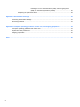
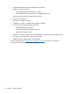
1 Product features Overview Figure 1-1 HP ProOne 400 G1 All-in-One The HP ProOne 400 G1 All-in-One offers the following features: ● Integrated All-in-One form factor ● 50.8-cm (19.
● Integrated Realtek RTL8151GH-CH GbE Ethernet Controller ● Wireless connectivity (optional): ◦ Intel Dual Band Wireless-N 7260, 802.11 a/b/g/n ◦ WLAN and Bluetooth Combo Card, 802.11 a/b/g/n Bluetooth® 4.0 ● Optional integrated webcam and dual microphone array ● Premium stereo speakers ● Optional 5-in-1 media card reader ● 6 USB ports: 1 USB 3.0, 1 USB 3.0 (fast-charging), 4 USB 2.
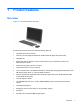
Front components Figure 1-2 Front components Table 1-1 Front Components Component Component 1 Dual microphone array (optional) 4 Power button 2 Webcam activity LED (with optional webcam) 5 High-performance stereo speakers 3 Webcam (optional) Front components 3
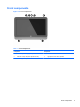
Side components Figure 1-3 Side components Table 1-2 Side components 4 Component Component 1 Optical disc drive eject button 6 HP 5-in-1 media card reader (optional) 2 Optical disc drive activity LED 7 USB 3.0 port 3 Tray-load optical disc drive 8 USB 3.
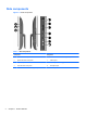
Rear components Figure 1-4 Rear components Table 1-3 Rear components Component Component 1 Access panel 6 Cable lock slot 2 Access panel security screw 7 Power supply connector 3 Security screw hole 8 RJ-45 Gigabit Ethernet port 4 DisplayPort port 9 (4) USB 2.
Keyboard features Figure 1-5 Keyboard features Table 1-4 Keyboard features 6 Component Component 1 Sleep 6 Mute Volume 2 Fast Reverse 7 Decrease Volume 3 Play/Pause 8 Increase Volume 4 Stop 9 Function 5 Fast Forward Chapter 1 Product features
Adjusting the stand This stand allows you to tilt the computer backward from 10 degrees to 25 degrees to set it to a comfortable angle. Figure 1-6 Adjusting tilt Serial number location The computer has a unique serial number and a product ID number that are located on the exterior of the computer. Keep these numbers available for use when contacting customer service for assistance.
2 Hardware repair and upgrade Warnings and cautions Before performing upgrades be sure to carefully read all of the applicable instructions, cautions, and warnings in this guide. WARNING! To reduce the risk of personal injury from electrical shock, hot surfaces, or fire: Disconnect the power cord from the wall outlet and allow the internal system components to cool before touching. Do not plug telecommunications or telephone connectors into the network interface controller (NIC) receptacles.
Connecting and disconnecting power Connecting power 1. Connect the peripheral cables to the appropriate ports. 2. Plug the female end of the power cord into the power supply brick (1). 3. Connect the other end of the power cord to an electrical outlet (2). 4. Connect the round end of the power supply cord to the power supply connector on the rear of the computer (3). Figure 2-1 Connecting power 5. Press the power button on the top of the computer to turn it on. Disconnecting power 1.
Installing a cable lock The cable lock slot enables you to secure your computer. A cable lock is a key lock device that has a wire cable attached. You attach one end of the cable to your desk (or other stationary object) and the other end of the cable to the cable lock slot on back of the computer. Secure the cable lock with the key. Figure 2-2 Installing a cable lock Installing an access panel security screw You may prevent access to internal components by securing the access panel.
Synchronizing the optional wireless keyboard and mouse The optional wireless keyboard and mouse are easy to set up. Just remove the battery tabs on both the keyboard and the mouse to activate the preinstalled batteries. NOTE: For better mouse battery life and performance, avoid using your mouse on a dark or highgloss surface, and turn mouse power off when not in use. To synchronize the wireless keyboard and mouse: 1.
Removing batteries from the optional wireless keyboard or mouse NOTE: The wireless keyboard and mouse are optional components. To remove batteries from the wireless keyboard, remove the battery door on the underside of the keyboard (1) and lift the batteries out of the battery compartment (2).
Attaching the computer to a mounting fixture The computer stand is secured to a VESA mount inside the computer chassis. You can remove the stand and install the computer on a wall, monitor arm, or other mounting fixture. Table 2-1 Computer dimensions (without stand) Computer dimensions (without stand) Height 339.4 mm 13.4 in Width 494.9 mm 19.5 in Depth 52 mm 2.0 in Minimum configuration 5.07 kg 11.2 lb With Options 5.36 kg 11.8 lb 100 mm x 100 mm 3.94 in x 3.
7. Rotate the bottom edge of the access panel up (2), and then lift the access panel off of the computer (3). Figure 2-7 Removing the access panel 8. Place the access panel down on a flat surface with the inside of the panel facing up. 9. Remove the four screws securing the stand to the access panel. Figure 2-8 Removing the stand NOTE: Save the screws together with the stand in case they are needed in the future. 10.
11. Rotate the bottom edge of the access panel down (2) and press it firmly onto the chassis until it locks into place. You will hear audible clicks as the latches click into place. Figure 2-9 Replacing the access panel The computer is now ready to be mounted to a wall, monitor arm, or other mounting fixture. Connecting a second display The DisplayPort connector on the rear of the computer allows you to connect a second display to the computer.
2. If your second display has a DisplayPort connector, connect a DisplayPort cable directly between the DisplayPort connector on the rear of the computer and the DisplayPort connector on the second display. Figure 2-10 Connecting a second display using a DisplayPort cable 3. If your second display does not have a DisplayPort connector, connect a DisplayPort video adapter to the DisplayPort connector of the computer. Then connect a cable (VGA, DVI.
Locating internal components The following sections contain procedures for removing and replacing these internal components: ● Optical disc drive ● Hard disc drive, solid state drive, or self-encrypting drive ● Battery ● Memory Figure 2-12 Locating internal components Component Component 1 Optical disc drive 3 Battery 2 Hard disc drive 4 Memory Removing and installing memory The computer comes with double data rate 3 synchronous dynamic random access memory (DDR3SDRAM) small outline dual
In addition, the computer supports: ● 1-Gbit, 2-Gbit, and 4-Gbit non-ECC memory technologies ● single-sided and double-sided SODIMMS ● SODIMMs constructed with x8 and x16 SDRAMs; SODIMMs constructed with x4 SDRAMs are not supported NOTE: The system will not operate properly if you install unsupported SODIMM memory. HP offers upgrade memory for this computer and advises that the consumer purchase it to avoid compatibility issues with unsupported third-party memory.
Populating SODIMM sockets The system will automatically operate in single channel mode, dual channel mode, or flex mode, depending on how the SODIMMs are installed. Refer to the following table to identify the SODIMM channel locations. Table 2-2 Identifying SODIMM locations Location System board label Channel Lower Socket SODIMM1 Channel A Upper Socket SODIMM3 Channel B ● The system will operate in single channel mode if the SODIMM sockets are populated in one channel only.
7. Rotate the bottom edge of the access panel up (2), and then lift the access panel off of the computer (3). Figure 2-13 Removing the access panel 8. Remove the three screws securing the VESA panel to the chassis (1), and then lift the panel out of the chassis (2).
9. Remove the three screws securing the fire enclosure shield to the chassis, and then rotate the shield out of the chassis. Figure 2-15 Removing the fire enclosure shield The memory modules can now be seen in the right side of the chassis.
10. To remove a memory module, press outward on the two latches on each side of the SODIMM (1), then pull the SODIMM out of the socket (2). Figure 2-17 Removing a memory module 11. To install a memory module, slide the SODIMM into the socket at approximately a 30° angle (1), then press the SODIMM down (2) so that the latches lock it in place. Figure 2-18 Installing a memory module NOTE: A memory module can be installed in only one way. Match the notch on the module with the tab on the memory socket. 12.
16. Rotate the bottom edge of the access panel down (2) and press it firmly onto the chassis until it locks into place. You will hear audible clicks as the latches click into place. Figure 2-19 Replacing the access panel 17. Place the computer in the upright position. 18. Reconnect the power cord and external devices. 19. Lock any security devices that were disengaged when the access panel was removed. 20. Turn on the computer.
NOTE: The lifetime of the lithium battery can be extended by plugging the computer into a live AC wall socket. The lithium battery is only used when the computer is NOT connected to AC power. HP encourages customers to recycle used electronic hardware, HP original print cartridges, and rechargeable batteries. For more information about recycling programs, go to http://www.hp.com/ recycle. 1. Remove all removable media, such as optical discs or USB flash drives, from the computer. 2.
8. Remove the three screws securing the VESA panel to the chassis (1), and then lift the panel out of the chassis (2).
9. Remove the three screws securing the fire enclosure shield to the chassis, and then rotate the shield out of the chassis. Figure 2-22 Removing the fire enclosure shield The battery can now be seen to the right of the fan. Figure 2-23 Locating the battery 10. To release the battery from its holder, squeeze the metal clamp that extends above one edge of the battery. When the battery pops up, lift it out (1).
11. To insert the new battery, slide one edge of the replacement battery under the holder’s lip with the positive side up. Push the other edge down until the clamp snaps over the other edge of the battery (2). Figure 2-24 Removing and replacing a coin cell battery 12. Engage the four hooks on the right edge of the fire enclosure shield with the matching slots on the right side of the chassis and rotate the fire enclosure shield down onto the chassis. 13.
17. Place the computer in the upright position. 18. Reconnect the power cord and external devices. 19. Lock any security devices that were disengaged when the access panel was removed. 20. Turn on the computer. 21. Reset the date and time, your passwords, and any special system setups using Computer Setup. Replacing drives Replacing a hard drive The hard drive is located behind the access panel on the lower left side of the computer (when viewed from behind). The drive is housed in a removable cage.
7. Rotate the bottom edge of the access panel up (2), and then lift the access panel off of the computer (3). Figure 2-26 Removing the access panel The hard drive cage can now be seen in the lower left side of the chassis. Figure 2-27 Locating the hard drive cage 8. Loosen the captive screw securing the hard drive cage in the chassis (1).
9. Slide the hard drive cage left, and then lift it out of the chassis (2). Figure 2-28 Removing the hard drive cage 10. Remove the four mounting screws (1) securing the 3.5-inch hard drive in the hard drive cage. Be sure to keep the screws together with the blue rubber grommets to use to install a replacement drive. 11. Slide the 3.5-inch hard drive out of the hard drive cage (2).
Removing a 2.5-inch solid state drive (SSD), self-encrypting drive (SED), or solid state hybrid drive (SSHD) 1. Remove all removable media, such as optical discs or USB flash drives, from the computer. 2. Turn off the computer properly through the operating system, then turn off any external devices. 3. Disconnect the power cord from the power outlet and disconnect any external devices.
8. Loosen the captive screw securing the hard drive cage in the chassis (1). 9. Slide the hard drive cage left, and then lift it out of the chassis (2). Figure 2-32 Removing the hard drive cage 10. Remove the four mounting screws (1) securing the 2.5-inch drive adapter in the hard drive cage. Be sure to keep the screws together with the blue rubber grommets to use to install a replacement drive. 11. Slide the 2.5-inch drive adapter out of the hard drive cage (2). Figure 2-33 Removing the drive cage 12.
13. Slide the 2.5-inch hard drive out of the drive adapter (2). Figure 2-34 Removing the 2.5-inch drive adapter from the drive cage For instructions on installing a hard drive, see Installing a hard drive on page 34.
Installing a hard drive ● Installing a 3.5-inch hard drive ● Installing a 2.5-inch solid state drive (SSD), self-encrypting drive (SED), or solid state hybrid drive (SSHD) Installing a 3.5-inch hard drive 1. Slide the new 3.5-inch hard drive into the hard drive cage (1). Be sure that the hard drive connector is facing up at the open end of the drive. 2. Screw the four mounting screws through the sides of the hard drive cage into the 3.5-inch hard drive (2).
5. Set the top edge of the access panel down on the top edge of the computer chassis (1). Be sure to align the hooks on the underside of the top edge of the access panel with the top edge of the computer. 6. Rotate the bottom edge of the access panel down (2) and press it firmly onto the chassis until it locks into place. You will hear audible clicks as the latches click into place. Figure 2-37 Replacing the access panel 7. Place the computer in the upright position. 8.
Installing a 2.5-inch solid state drive (SSD), self-encrypting drive (SED), or solid state hybrid drive (SSHD) 1. Insert the 2.5-inch solid state drive (SSD), self-encrypting drive (SED), or solid state hybrid drive (SSHD) into the 2.5-inch drive adapter (1). Be sure that the connector is at the opening of the adapter. 2. Fasten the four screws (2) to secure the 2.5-inch solid state drive (SSD), self-encrypting drive (SED), or solid state hybrid drive (SSHD) in the 2.5-inch drive adapter.
6. Tighten the captive screw (2) to secure the hard drive cage in the chassis. Figure 2-40 Installing the hard drive cage 7. Set the top edge of the access panel down on the top edge of the computer chassis (1). Be sure to align the hooks on the underside of the top edge of the access panel with the top edge of the computer. 8. Rotate the bottom edge of the access panel down (2) and press it firmly onto the chassis until it locks into place. You will hear audible clicks as the latches click into place.
Replacing the optical disc drive The optical disc drive is located above the hard drive on the left side of the computer (when viewed from behind). 1. Remove all removable media, such as optical discs or USB flash drives, from the computer. 2. Turn off the computer properly through the operating system, then turn off any external devices. 3. Disconnect the power cord from the power outlet and disconnect any external devices.
7. Rotate the bottom edge of the access panel up (2), and then lift the access panel off of the computer (3). Figure 2-42 Removing the access panel The optical disc drive can now be seen in the upper left side of the chassis. Figure 2-43 Locating the optical disc drive 8. Remove the screw through the optical disc drive bracket that secures the optical disc drive to the chassis (1).
9. Slide the optical disc drive left (2) to remove it from the chassis. Figure 2-44 Removing the optical disc drive 10. Remove the two screws attaching the optical disc drive bracket to the optical disc drive.
11. Attach the optical disc drive bracket to the new optical disc drive by screwing the two screws through the bracket into the new drive. Figure 2-46 Installing the optical disc drive bracket 12. Place the new optical disc drive into the chassis and push the drive in firmly until it snaps into place (1). NOTE: The optical disc drive can be installed in only one way. 13. Fasten the screw to the inside tab of the optical disc drive to secure the drive to the chassis.
15. Rotate the bottom edge of the access panel down (2) and press it firmly onto the chassis until it locks into place. You will hear audible clicks as the latches click into place. Figure 2-48 Replacing the access panel 16. Place the computer in the upright position. 17. Reconnect the power cord and external devices. 18. Lock any security devices that were disengaged when the access panel was removed. 19. Turn on the computer.
A Electrostatic discharge A discharge of static electricity from a finger or other conductor may damage system boards or other static-sensitive devices. This type of damage may reduce the life expectancy of the device. Preventing electrostatic damage To prevent electrostatic damage, observe the following precautions: ● Avoid hand contact by transporting and storing products in static-safe containers. ● Keep electrostatic-sensitive parts in their containers until they arrive at static-free workstations.
B Computer operating guidelines, routine care, and shipping preparation Computer operating guidelines and routine care Follow these guidelines to properly set up and care for the computer: 44 ● Keep the computer away from excessive moisture, direct sunlight, and extremes of heat and cold. ● Operate the computer on a sturdy, level surface. Leave a 10.2-cm (4-inch) clearance on all vented sides of the computer to permit the required airflow.
Optical disc drive precautions Be sure to observe the following guidelines while operating or cleaning the optical disc drive. ● Do not move the drive during operation. This may cause it to malfunction during reading. ● Avoid exposing the drive to sudden changes in temperature, as condensation may form inside the unit. If the temperature suddenly changes while the drive is on, wait at least one hour before you turn off the power. If you operate the unit immediately, it may malfunction while reading.
Index A additional information replacing 28 self-encrypting drive (SED) 28 solid state drive (SSD) 28 solid state hybrid drive (SSHD) 28 types 28 8 B battery, replacing 23 C components front 3 internal 17 rear 5 side 4 computer operating guidelines 44 D DisplayPort video adapter, connecting 15 drive 2.5-inch, installing 36 2.5-inch, removing 31 3.5-inch, installing 34 3.
solid state hybrid drive (SSHD) 2.5-inch, installing 36 2.