HP A-F1000-A-EI/A-F1000-S-EI VPN Firewall Installation Guide Part number: 5998-1415 Document version: 6PW100-20110909
Legal and notice information © Copyright 2011 Hewlett-Packard Development Company, L.P. No part of this documentation may be reproduced or transmitted in any form or by any means without prior written consent of Hewlett-Packard Development Company, L.P. The information contained herein is subject to change without notice.
Contents Product overview·························································································································································· 1 Front panel view································································································································································1 Rear panel view ·······································································································································
Configuring NAT ··················································································································································· 27 Completing the configuration wizard ················································································································· 29 Hardware management and maintenance ··············································································································30 Displaying detailed information about the
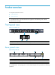
Product overview This chapter includes these sections: • Front panel view • Rear panel view NOTE: The A-F1000-S-EI and A-F1000-A-EI share the same appearance. The following section uses the A-F1000-A-EI as an example.
Table 1 Description of the “OPEN BOOK” mark Operation Reference Grounding the firewall Grounding the firewall Connecting the firewall to the power source Installing the power supply and connecting the power cord 2
Preparing for installation This chapter includes these sections: • Safety recommendations • Examining the installation site • Installation tools • Accessories supplied by the firewall • Checklist before installation Safety recommendations To avoid possible bodily injury and equipment damage, read the safety recommendations in this chapter carefully before installing an A-F1000-A-EI/A-F1000-S-EI firewall. The recommendations do not cover every possible hazardous condition.
• If there are two power inputs, disconnect the two power inputs to power off the firewall. • Do not work alone when the firewall has power. • Always check that the power has been disconnected. Safety with laser • Do not stare into the optical port or fiber connector because the laser light emitted from the optical fiber may hurt your eyes. • Install a dust plug on the transceiver module to avoid damage to the transceiver module.
Altitude Table 4 Altitude requirements Item Altitude Operating altitude –60 m (–196.85 ft) to 3 km (1.86 miles) Storage altitude –60 m (–196.85 ft) to 4.5km(2.8 miles) Cleanness Dust buildup on the chassis may result in electrostatic adsorption, which causes poor contact of metal components and contact points, especially when indoor relative humidity is low. In the worst case, electrostatic adsorption can cause communication failure.
• Make sure there is enough space (greater than 10 cm (3.94 in)) around the air intake and outlet vents on the firewall for good ventilation. • Make sure the installation site has a good cooling system. ESD prevention To prevent electrostatic discharge (ESD), note the following guidelines: • Make sure that the firewall and the floor are well grounded. • Take dust-proof measures for the equipment room. • Maintain the humidity and temperature at a proper level.
CAUTION: • Check the resistance of the ESD-preventive wrist strap for safety. The resistance reading should be in the range of 1 to 10 megohm (Mohm) between human body and the ground. • No ESD-preventive wrist strap is provided with the A-F1000-A-EI/A-F1000-S-EI firewall. Prepare it yourself. EMI To prevent electromagnetic interference (EMI) when you use the firewall, note the following guidelines: • Take measures against interference from the power grid.
RJ45 crimping pliers Multimeter Network cable tester Mark pen ESD-preventive wrist strap NOTE: No installation tool or ESD-preventive wrist strap is provided with the firewall. Prepare them yourself. Accessories supplied by the firewall Console cable Grounding cable Feet Mounting bracket Checklist before installation Table 7 Checklist before installation Item Requirements • There is a minimum clearance of 10 cm (3.
Item Requirements • Take effective measures to protect the power system from the power grid system. • Separate the protection ground of the firewall from the EMI prevention grounding device or lightning protection grounding device as far as possible. • Keep the firewall far away from radio stations, radar and high-frequency devices working in high current. • Use electromagnetic shielding when necessary. Lightning protection Electricity safety • The grounding cable of the chassis is well grounded.
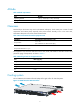
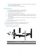
Installing the firewall This chapter includes these sections: • Installation flow • Installing the firewall in a 19-inch rack • Grounding the firewall • Installing an interface module • Connecting Ethernet cables • Installing the power supply and connecting the power cord Installation flow Figure 5 HP firewall installation flow Start Install the firewall to a 19' rack Ground the firewall Install an interface module Connecting Ethernet cables Connect the power cord End Installing the firewal
Figure 6 Install cage nuts Step2 Install the mounting brackets to both sides of the front panel, as shown in Figure 7. Figure 7 Install the mounting brackets to both sides of the front panel Step3 Supporting the firewall bottom with one hand, push the firewall into the rack horizontally. Step4 Fix the firewall horizontally by fastening the front mounting brackets at both sides to the rack with appropriate pan head screws.
Figure 8 Fix the firewall to the rack Grounding the firewall WARNING! Correctly connecting the firewall grounding cable is crucial to lightning protection and EMI protection. Follow these steps to connect the grounding cable: Step1 Remove the grounding screw from the rear panel of the firewall chassis. Step2 Attach the grounding screw to the OT terminal of the grounding cable. Step3 Use a screwdriver to fasten the grounding screw into the grounding screw hole.
Figure 9 Connect the grounding cable 1 (1) OT terminal Installing an interface module CAUTION: A NSQ1XS2U0 interface module can be installed only to slot 1. Follow these steps to install an interface module: Step1 Remove the filler panel on slot 1. Use a Phillips screwdriver to loosen the fastening screws on the filler panel, and then remove the filler panel. Step2 Push the interface module slowly along the guide rails into the slot until it touches the slot bottom.
Connecting Ethernet cables Connecting a copper Ethernet cable Follow these steps to connect a copper Ethernet cable: Step1 Plug one end of an Ethernet twisted pair cable into the copper Ethernet port (RJ-45 port) to be connected on the firewall. Step2 Plug the other end of the cable into the RJ-45 port of the peer device. Step3 After the firewall is powered on, check the status LED of the port. If the LED is solid green, you can be sure that the link is connected.
Step2 Plug the transceiver module into the SFP port of the firewall, as shown in Figure 12. Figure 12 Install the transceiver module To unplug the transceiver module, you should move the pull latch to the horizontal position, and then pull the transceiver module out. Step3 Remove the dust cap from the transceiver module and the protective caps from the fibers.
Installing the power supply and connecting the power cord NOTE: • No AC power supply or DC power supply is provided with the firewall. • You can install two power supplies in your firewall, and they must be the same model. Installing a power supply The procedures for installing an AC power supply and DC power supply are the same. The following uses an AC power supply as an example. Step1 Locate the slot to install the power supply.
Figure 15 Connect an AC power cord Connecting the DC power cable Follow these steps to connect the DC power cable: Step1 Insert the DC power cable connector with the upside up (if the upside is down, you cannot insert the connector smoothly), as shown in callout 1 of Figure 16. Step2 Fasten the two strain-relief screws on the power cable connector clockwise to secure the connector to the socket, as shown in callout 2 of Figure 16.
Logging in to the firewall and configuring basic settings This chapter includes these sections: • Logging in to the firewall through the console port • Powering on the firewall • Logging in to the firewall through Telnet • Logging to the firewall through a web browser • Performing basic settings for the firewall This chapter describes only the commonly used methods for logging in to the firewall.
CAUTION: • When you connect a PC to a powered-on firewall, connect the DB-9 connector of the console cable to the PC before connecting the RJ-45 connector to the firewall. • When you disconnect a PC from a powered-on firewall, disconnect the DB-9 connector of the console cable from the PC after disconnecting the RJ-45 connector from the firewall.
Figure 19 Set the serial port used by the HyperTerminal connection Step3 Click OK after selecting a serial port and the following dialog box appears. Set Bits per second to 9600, Data bits to 8, Parity to None, Stop bits to 1, and Flow control to None. Figure 20 Set the serial port parameters Step4 Click OK after setting the serial port parameters and the system enters the following interface.
Figure 21 HyperTerminal window Step5 Click Properties in the HyperTerminal window to enter the aaa Properties dialog box. Click the Settings tab, set the Emulation to VT100, and then click OK. Powering on the firewall Checking before power-on Before powering on the firewall, verify the following items: • The power cord and grounding cable are properly connected. • The power source matches that required by the firewall.
Logging in to the firewall through Telnet NOTE: For more information about the Telnet login, see the configuration guides for the firewalls. You can use the default information to log in to the A-F1000-A-EI/A-F1000-S-EI firewall. The default login information includes: • Username: admin • Password: admin • IP address of port GigabitEthernet 0/0: 192.168.0.
Launch the web browser on the PC. Type 192.168.0.1 in the address bar and press Enter. The login dialog box appears, as shown in Figure 22. In this dialog box, enter your user name (admin), password (admin), verify code and click Login. Figure 22 Web login dialog box Then, the web interface of the A-F1000-A-EI/A-F1000-S-EI firewall appears. Performing basic settings for the firewall This section describes the fast configuration by using the basic configuration wizard.
Figure 23 Basic configuration wizard: 1/6 Configuring the system name and user password Click Next on the first page of the basic configuration wizard to enter the basic information configuration page, as shown in Figure 24.
Table 8 Basic information configuration items Item Description Sysname Set the system name. By default, the system name of the firewall is HP. Modify Current User Password Specify whether to modify the login password of the current user. New Password To modify the password of the current user, set the new password and the confirm password, and the two passwords must be identical. Confirm Password By default, the firewall login username and password are both admin.
Item Description Specify whether to enable HTTP on the device, and set the HTTP port number. Enabled by default. IMPORTANT: HTTP • If the current user has logged in to the web interface through HTTP, disabling HTTP or modifying the HTTP port number will result in disconnection with the device; therefore, perform the operation with caution. • When you modify a port number, ensure that the port number is not used by another service.
Figure 26 Basic configuration wizard: 4/6 (interface IP configuration) Table 10 Interface IP address configuration items Item Description Set the approach for obtaining the IP address, including: • None: The IP address of the interface is not specified, that is, the interface has no IP address. • Static Address: Specify the IP address for the interface IP Configuration manually; if you select this item, you need to specify both the IP address and the mask.
Figure 27 Basic configuration wizard: 5/6 (NAT configuration) Table 11 NAT configuration items Item Description Interface Select an interface on which the NAT configuration will be applied. Generally, it is the outgoing interface of the device. Specify whether to enable dynamic NAT on the interface. Dynamic NAT If dynamic NAT is enabled, the IP address of the interface will be used as the IP address of a matched packet after the translation. By default, dynamic NAT is disabled.
Item Description Internal IP: Port If the internal server is enabled, set the IP address and service port number for the server on the internal LAN. Completing the configuration wizard Click Next on the NAT configuration page to enter the page shown in Figure 28. Figure 28 Basic configuration wizard: 6/6 This page lists all configurations you have made in the basic configuration wizard. Confirm the configurations.
Hardware management and maintenance This chapter includes these sections: • Displaying detailed information about the firewall • Displaying software and hardware version information of the firewall • Displaying the electrical label information of the firewall • Displaying the CPU usage of the firewall • Displaying the memory usage of the firewall • Displaying the operational status of the fans • Displaying the operational status of a power supply • Displaying the temperature information of th
Status :Absent The SubCard2 on Board0: Status :Absent Displaying software and hardware version information of the firewall Use the display version command to display software and hardware version information of the firewall. display version HP Comware Platform Software Comware Software, Version 5.20, Ess 3716 Copyright (c) 2010-2011 Hewlett-Packard Development Company, L.P.
MANUFACTURING_DATE :2010-06-29 VENDOR_NAME :HP Displaying the CPU usage of the firewall Use the display cpu-usage command to display the CPU usage of a firewall. display cpu-usage Unit CPU usage: 4% in last 5 seconds 4% in last 1 minute 4% in last 5 minutes Displaying the memory usage of the firewall Use the display memory command to display the memory usage of a firewall.
Table 13 Output description Field Power Description 1 Number of the power supply The power supply state: • Normal—The power supply is operating properly. • AbNormal—The power supply is not in position. • Fault—The power supply fails. Status Displaying the temperature information of the firewall Use the display environment command to display the temperature information of the firewall.
• Display the operational statistics of each functional module of the firewall. The output is too much and omitted here. display diagnostic-information Save or display diagnostic information (Y=save, N=display)? [Y/N]:n ================================================================= ===============running CPU usage information=============== ================================================================= ===== Current CPU usage info ===== CPU Usage Stat.
• Use the reboot command to reboot a firewall. • Enable the scheduled reboot function at the CLI. You can set a time at which the firewall can automatically reboot, or set a delay so that the firewall can automatically reboot within the delay. • Power on the firewall after powering it off, which is also called hard reboot or cold start. Powering off a running firewall causes data loss and hardware damages, and therefore is not recommended.
Troubleshooting This chapter includes these sections: • Power supply system failure • Fan failure • Configuration terminal problems • Password loss • Cooling system failure • Interface module failure NOTE: • The barcode stuck on the firewall chassis contains production and servicing information. Before you return a faulty firewall for serving, provide the barcode information of the firewall to your local sales agent.
Configuration terminal problems If the configuration environment setup is correct, the configuration terminal displays boot information when the firewall is powered on. If the setup is incorrect, the configuration terminal displays nothing or garbled text. No terminal display If the configuration terminal displays nothing when the firewall is powered on, check the following items: • The power supply system works properly. • The console cable is properly connected.
When you set the password by using the set authentication password { cipher | simple } password command, follow these guidelines. • If the cipher keyword is specified, the password is stored in cipher text. You cannot view the password by using the display current-configuration command. • If the simple keyword is specified, the password is stored in plain text. You can use the display current-configuration command to view the password in the current configuration.
Cooling system failure When the temperature inside the firewall exceeds 45°C (113°F), the cooling system may have failed. Follow these steps to troubleshoot the cooling system: Step1 Check whether the fans are running properly. Step2 Check whether the working environment of the firewall is well ventilated.
Appendix A Technical specifications Dimensions and weight Table 14 Dimensions and weight Specification Item A-F1000-A-EI/A-F1000-S-EI Dimensions without feet and rack-mounting ears (H × W × D) 44.2 × 442 × 442.6 mm (1.74 × 17.40 × 17.43 in) Weight 5.5 kg (12.
Power input Table 17 Power input specifications Remarks Item AC DC A-F1000-A-EI/A-F1000-S-EI Rated voltage range 100 to 240 VAC; 50/60 Hz Maximum input current 2A Maximum output power 150 W Rated voltage range –48VDC to –60VDC Maximum input current 6A Maximum output power 150 W NOTE: No AC power supply or DC power supply is provided with the firewall.
1. Technical specifications for copper Ethernet ports Table 19 Technical specifications for copper Ethernet ports Item Specification Connector RJ-45 Port Autosensing (Ethernet does not support MDI/MDIX autosensing when working in the forced mode) Ethernet_II Frame format Ethernet_SNAP Rate and duplex mode 2.
Appendix B LEDs Front panel LEDs Figure 29 Front panel LEDs Table 21 Description of front panel LEDs LED Copper Ethernet interface LEDs Yellow/Green Ethernet link state/Data transmission state LEDs (LINK/ACT) Status Meaning OFF No link is present. Solid green A 1000 Mbps link is present. Solid yellow A 10/100 Mbps link is present. Solid green A link is present. Flashing green Data is being received or transmitted. OFF No link is present. OFF The firewall is powered off or faulty.
LED PWR2 Green Status Meaning OFF Power supply 2 is not in position or power input is not available. ON Power supply 2 is operational.
Appendix C Interface module NSQ1XS2U0 Introduction An NSQ1XS2U0 is a Layer 3 10-Gigabit Ethernet interface module, and provides two SFP+ optical interfaces. CAUTION: An NSQ1XS2U0 can be installed only in SLOT1 of the firewall. Front panel Figure 30 Front panel of NSQ1XS2U0 (1) Captive screw (2) SFP+ port (3) LINK/ACT LED LED Table 22 Description of the LED on the front panel of NSQ1XS2U0 Status LINK/ACT Meaning Off No link is present. On A 10 Gbps link is present.
Model Central wavelen gth Fiber mode Fiber diameter (μm) Bandwi dth (MHz*k m) Max transmissi on distance 400 66 m (216.54 ft) 200 33 m (108.27 ft) 160 26 m (85.30 ft) 500 220 m (721.79 ft) 500 220 m (721.79 ft) 400 100 m (328.08 ft) — 10 km (6.21 miles) 62.5/125 62.5/125 SFP-XG-L X220-M M1310 MMF 50/125 1310 nm SFP-XG-L X-SM131 0 SMF 9/125 Specification (dBm) Optical transmit power Receivi ng sensitiv ity Optic al satur ation –6.5 to +0.5 ≤–6.5 +1.5 –8.2 to + 0.5 ≤–10.
Appendix D AC power cables used in different countries or regions 10A AC power cables used in different countries or regions Table 24 10A AC power cables used in different countries or regions 1 2 Connect or type Code (Length) Countries or regions where the type of power cables conforms to local safety regulations and can be used legally I type 04041104 (3 m, i.e., 9.
F type 4 5 6 04041056 (3 m, i.e., 9.8 ft) Holland, Denmark, Sweden, Finland, Norway, Germany, France, Austria, Belgium, and Italy Indonesia, Turkey, Russia, and CIS Connector outline Power cable outline Connect or type Code (Length) Countries or regions where the type of power cables conforms to local safety regulations and can be used legally Other countries or regions using this type of power cables G type 04040890 (3 m, i.e., 9.8 ft) U.K.
7 8 9 Connector outline Power cable outline Connect or type Code (Length) Countries or regions where the type of power cables conforms to local safety regulations and can be used legally I type 04040888 (3 m, i.e., 9.8 ft) Australia Connector outline Power cable outline Connect or type Code (Length) Countries or regions where the type of power cables conforms to local safety regulations and can be used legally J type 04041119 (3 m, i.e., 9.
16A AC power cables used in different countries or regions Table 25 16A AC power cables used in different countries or regions 1 Connector type Code (Length) Countries or regions where the type of power cables conforms to local safety regulations and can be used legally I type 04043396 (3 m, i.e., 9.
F type 4 5 6 0404A061 (3 m, i.e., 9.8 ft) Holland, Denmark, Sweden, Finland, Norway, Germany, France, Austria, Belgium, and Italy Indonesia, Turkey, Russia, and CIS Connector outline Power cable outline Connector type Code (Length) Countries or regions where the type of power cables conforms to local safety regulations and can be used legally Other countries or regions using this type of power cables G type 0404A060 (3 m, i.e., 9.8 ft) U.K.
I type 0404A01A (3 m, i.e., 9.
Support and other resources Contacting HP For worldwide technical support information, see the HP support website: http://www.hp.
Conventions This section describes the conventions used in this documentation set. Command conventions Convention Description Boldface Bold text represents commands and keywords that you enter literally as shown. Italic Italic text represents arguments that you replace with actual values. [] Square brackets enclose syntax choices (keywords or arguments) that are optional. { x | y | ... } Braces enclose a set of required syntax choices separated by vertical bars, from which you select one.
Network topology icons Represents a generic network device, such as a router, switch, or firewall. Represents a routing-capable device, such as a router or Layer 3 switch. Represents a generic switch, such as a Layer 2 or Layer 3 switch, or a router that supports Layer 2 forwarding and other Layer 2 features. Port numbering in examples The port numbers in this document are for illustration only and might be unavailable on your device.
Index ACDEFGILNPRS A Grounding the firewall,12 Accessories supplied by the firewall,8 I C Installation flow,10 Installation tools,7 Checklist before installation,8 Installing an interface module,13 Combo interfaces,41 Installing the firewall in a 19-inch rack,10 Configuration terminal problems,37 Installing the power supply and connecting the power cord,16 Connecting Ethernet cables,14 Console port,41 Interface module failure,39 Contacting HP,53 L Conventions,54 Logging in to the firewall t