Hardware Reference Guide - dc7900 Series Ultra-Slim Desktop HP Compaq Business PC
© Copyright 2008 Hewlett-Packard Development Company, L.P. The information contained herein is subject to change without notice. Microsoft, Windows, and Windows Vista are either trademarks or registered trademarks of Microsoft Corporation in the United States and/or other countries. The only warranties for HP products and services are set forth in the express warranty statements accompanying such products and services. Nothing herein should be construed as constituting an additional warranty.
About This Book This guide provides basic information for upgrading this computer model. WARNING! Text set off in this manner indicates that failure to follow directions could result in bodily harm or loss of life. CAUTION: Text set off in this manner indicates that failure to follow directions could result in damage to equipment or loss of information. NOTE: Text set off in this manner provides important supplemental information.
iv About This Book ENWW
Table of contents 1 Product Features Standard Configuration Features ......................................................................................................... 1 Front Panel Components ..................................................................................................................... 2 Rear Panel Components ...................................................................................................................... 3 Keyboard .......................................
Appendix C Security Lock Provisions Installing a Security Lock .................................................................................................................... 34 Cable Lock ......................................................................................................................... 34 Padlock .............................................................................................................................. 35 HP Business PC Security Lock ..........................
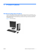
1 Product Features Standard Configuration Features The HP Compaq Ultra-Slim Desktop computer comes with features that may vary depending on the model. For a complete listing of the hardware and software installed in the computer, run the diagnostic utility (included on some computer models only). Instructions for using the utility are provided in the Troubleshooting Guide.
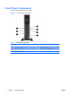
Front Panel Components Drive configuration may vary by model.
Rear Panel Components Figure 1-3 Rear Panel Components Table 1-2 Rear Panel Components 1 Power Cord Connector 6 VGA Monitor Connector (blue) 2 DisplayPort Monitor Connector 7 PS/2 Mouse Connector (green) 3 PS/2 Keyboard Connector (purple) 8 RJ-45 Network Connector 4 Universal Serial Bus (USB) (6) 9 Line-In Audio Connector (blue) 5 Line-Out Connector for powered audio devices (green) NOTE: Arrangement and number of connectors may vary by model.
Keyboard Figure 1-4 Keyboard Components Table 1-3 Keyboard Components 1 4 1 Function Keys Perform special functions depending on the software application being used. 2 Editing Keys Include the following: Insert, Home, Page Up, Delete, End, and Page Down. 3 Status Lights Indicate the status of the computer and keyboard settings (Num Lock, Caps Lock, and Scroll Lock). 4 Numeric Keys Work like a calculator keypad. 5 Arrow Keys Used to navigate through a document or Web site.
Using the Windows Logo Key Use the Windows Logo key in combination with other keys to perform certain functions available in the Windows operating system. Refer to Keyboard on page 4 to identify the Windows Logo key. Table 1-4 Windows Logo Key Functions The following Windows Logo Key functions are available in Microsoft Windows XP and Microsoft Windows Vista.
Serial Number Location Each computer has a unique serial number and a product ID that are located on the top of the computer when it is in the tower configuration. Keep these numbers available for use when contacting customer service for assistance.
2 Hardware Upgrades Serviceability Features The computer includes features that make it easy to upgrade and service. No tools are needed for most of the installation procedures described in this chapter. Warnings and Cautions Before performing upgrades be sure to carefully read all of the applicable instructions, cautions, and warnings in this guide.
Connecting the Power Cord When connecting the power supply, it is important to follow the steps below to ensure the power cord does not pull free from the computer. 1. Connect the power cord to the power supply connector on the rear of the computer (1). 2. Insert the power cord retainer clip into a slot on the air vent to prevent the cord from becoming disconnected from the computer (2). 3. Bundle any excess power cord with the supplied strap (3). 4.
Removing the Computer Access Panel To access internal components, you must remove the access panel: 1. Remove/disengage any security devices that prohibit opening the computer. 2. Remove all removable media, such as a compact disc, from the computer. 3. Turn off the computer properly through the operating system, then turn off any external devices. 4. Disconnect the power cord from the power outlet and disconnect any external devices.
Replacing the Computer Access Panel 1. Align the tabs on the panel with the slots on the chassis then slide the panel towards the rear of the chassis until it stops (1). 2. Tighten the thumbscrew to secure the access panel (2).
Removing and Replacing the Front Bezel 1. Remove/disengage any security devices that prohibit opening the computer. 2. Remove all removable media, such as a compact disc, from the computer. 3. Turn off the computer properly through the operating system, then turn off any external devices. 4. Disconnect the power cord from the power outlet and disconnect any external devices.
8. Press the two release tabs on the inside of the bezel towards the right side of the computer (1) and rotate the bezel off from right to left (2). Figure 2-5 Removing the Front Bezel 9. Replace the fan shroud. To replace the front bezel: 1. Slide the hooks on the left side of the bezel into the slots on the chassis (1) then press the right side of the bezel onto the chassis so that the latches snap in place (2). Figure 2-6 Replacing the Front Bezel 12 2. Replace the access panel. 3.
4. Reconnect the power cord and turn on the computer. 5. Lock any security devices that were disengaged when the access panel was removed. Removing a Bezel Blank On some models, there is a bezel blank covering the external drive bay that needs to be removed before installing a drive. To remove a bezel blank: 1. Remove the front bezel. 2. Push the two retaining tabs that hold the bezel blank in place towards the outer right edge of the bezel (1) and pull the bezel blank inwards to remove it (2).
Changing from Desktop to Tower Configuration 1. Remove/disengage any security devices that prohibit opening the computer. 2. Remove all removable media, such as a compact disc, from the computer. 3. Turn off the computer properly through the operating system, then turn off any external devices. 4. Disconnect the power cord from the power outlet and disconnect any external devices.
12. Place the computer firmly down into the stand. Figure 2-9 Placing the Computer on the Stand 13. Reconnect the external equipment, plug the power cord into a power outlet, and turn the computer on. 14. Lock any security devices that were disengaged when the computer cover or access panel was removed. To change from the tower configuration to the desktop configuration, reverse the previous steps.
Installing Additional Memory The computer comes with double data rate 2 synchronous dynamic random access memory (DDR2SDRAM) small outline dual inline memory modules (SODIMMs). SODIMMs The memory sockets on the system board can be populated with up to two industry-standard SODIMMs. These memory sockets are populated with at least one preinstalled SODIMM. To achieve the maximum memory support, you can populate the system board with up to 8-GB of memory.
Populating SODIMM Sockets There are two SODIMM sockets on the system board, with one socket per channel. The sockets are labeled DIMM1 and DIMM3. The DIMM1 socket operates in memory channel A. The DIMM3 socket operates in memory channel B. Figure 2-10 SODIMM Socket Locations Table 2-1 SODIMM Socket Locations Item Description Socket Color 1 SODIMM1 socket, Channel A Black 2 SODIMM3 socket, Channel B White NOTE: A SODIMM must occupy the black DIMM1 socket.
Installing SODIMMs CAUTION: You must disconnect the power cord before adding or removing memory modules. Regardless of the power-on state, voltage is always supplied to the memory modules as long as the computer is plugged into an active AC outlet. Adding or removing memory modules while voltage is present may cause irreparable damage to the memory modules or system board. The memory module sockets have gold-plated metal contacts.
8. If you are adding a second SODIMM, remove the SODIMM from the top DIMM1 socket to access the bottom DIMM3 socket. Press outward on the two latches on each side of the SODIMM (1) then pull the SODIMM out of the socket (2). Figure 2-11 Removing a SODIMM 9. Slide the new SODIMM into the socket at approximately a 30° angle (1) then press the SODIMM down (2) so that the latches lock it in place. Figure 2-12 Installing a SODIMM NOTE: A memory module can be installed in only one way.
12. If the computer was on a stand, replace the stand. 13. Reconnect the power cord and turn on the computer. 14. Lock any security devices that were disengaged when the computer cover or access panel was removed. The computer automatically recognizes the additional memory when you turn on the computer. Replacing the Optical Drive The Ultra-Slim Desktop uses a slimline Serial ATA (SATA) optical drive. Removing the Existing Optical Drive 1.
Preparing the New Optical Drive Before the new optical drive can be used, the release latch must be attached. 1. Peel the backing off the adhesive on the release latch. 2. Without allowing the release latch to touch the optical drive, carefully align the holes on the release latch with the pins on the side of the optical drive. Make sure the release latch is oriented properly. 3. Insert the pin at the front of the optical drive into the hole at the end of the release latch, and press firmly. 4.
Installing the New Optical Drive NOTE: If you are installing an optical drive in a bay that did not previously have a drive in it, you must remove the access panel and the bezel blank covering the opening of the bay before proceeding. Follow the procedures in Removing the Computer Access Panel on page 9 and Removing a Bezel Blank on page 13. 1. Attach the release latch to the new optical drive. Refer to Preparing the New Optical Drive on page 21. 2.
Replacing the Hard Drive NOTE: The Ultra-Slim Desktop supports only 2.5-inch Serial ATA (SATA) internal hard drives; parallel ATA (PATA) internal hard drives are not supported. Before you remove the old hard drive, be sure to back up the data from the old hard drive so that you can transfer the data to the new hard drive.
9. Lift the hard drive carrier straight up and out of the chassis. Figure 2-17 Removing the Hard Drive Carrier 10. To remove the hard drive from the carrier, remove the guide screw from the front left side of the carrier.
11. Slide the carrier back and remove the hard drive. Figure 2-19 Removing the Hard Drive 12. Transfer the three remaining guide screws (two on the right and one on the rear left) from the old drive to the new drive.
13. Align the guide screws with the slots on the carrier and slide the new hard drive into the carrier (1), then replace the guide screw on the front left of the carrier to secure the drive in the carrier (2). Figure 2-21 Installing the Hard Drive in the Carrier 14.
NOTE: No configuration of the SATA hard drive is necessary; the computer automatically recognizes it the next time you turn on the computer. After replacing the hard drive, use the Recovery Disc Set that you created when you initially set up the computer to restore the operating system, software drivers, and any software applications that were preinstalled on the computer. When the restore process has completed, reinstall any personal files that you backed up before replacing the hard drive.
Figure 2-24 Removing a Port Cover 28 Chapter 2 Hardware Upgrades ENWW
A Specifications Table A-1 Specifications Desktop Dimensions (in the desktop position) Height 2.60 in 6.6 cm Width 9.90 in 25.1 cm Depth 10.00 in 25.4 cm Approximate Weight 6.95 lb 3.
Table A-1 Specifications (continued) Rated Input Current (maximum)1 1 2.2A @ 100VAC 1.1A @ 200VAC This system utilizes an active power factor corrected external power supply. This allows the system to pass the CE mark requirements for use in the countries of the European Union. The active power factor corrected power supply also has the added benefit of not requiring an input voltage range select switch.
B Battery Replacement The battery that comes with the computer provides power to the real-time clock. When replacing the battery, use a battery equivalent to the battery originally installed in the computer. The computer comes with a 3-volt lithium coin cell battery. WARNING! The computer contains an internal lithium manganese dioxide battery. There is a risk of fire and burns if the battery is not handled properly. To reduce the risk of personal injury: Do not attempt to recharge the battery.
NOTE: On some computer models, it may be necessary to remove an internal component to gain access to the battery. 8. Depending on the type of battery holder on the system board, complete the following instructions to replace the battery. Type 1 a. Lift the battery out of its holder. Figure B-1 Removing a Coin Cell Battery (Type 1) b. Slide the replacement battery into position, positive side up. The battery holder automatically secures the battery in the proper position. Type 2 a.
b. Insert the new battery and position the clip back into place. Figure B-3 Removing a Coin Cell Battery (Type 3) NOTE: After the battery has been replaced, use the following steps to complete this procedure. 9. Replace the access panel. 10. If the computer was on a stand, replace the stand. 11. Reconnect the power cord and turn on the computer. 12. Reset the date and time, your passwords, and any special system setups, using Computer Setup.
C Security Lock Provisions NOTE: For information on data security features, refer to the Computer Setup (F10) Utility Guide, the Desktop Management Guide, and the HP ProtectTools Security Manager Guide (some models) at http://www.hp.com. The security locks displayed below and on the following pages can be used to secure the computer. Installing a Security Lock Cable Lock There are two cable lock slots on the rear of the computer. The slot next to the thumbscrew should be used when there is no port cover.
Figure C-2 Installing a Cable with a Port Cover Installed Padlock Figure C-3 Installing a Padlock ENWW Installing a Security Lock 35
HP Business PC Security Lock 1. Fasten the security cable by looping it around a stationary object. Figure C-4 Securing the Cable to a Fixed Object 2. Thread the keyboard and mouse cables through the lock.
3. Screw the lock to the chassis using the screw provided. Figure C-6 Attaching the Lock to the Chassis 4. Insert the plug end of the security cable into the lock (1) and push the button in (2) to engage the lock. Use the key provided to disengage the lock.
D Electrostatic Discharge A discharge of static electricity from a finger or other conductor may damage system boards or other static-sensitive devices. This type of damage may reduce the life expectancy of the device. Preventing Electrostatic Damage To prevent electrostatic damage, observe the following precautions: ● Avoid hand contact by transporting and storing products in static-safe containers.
E Computer Operating Guidelines, Routine Care and Shipping Preparation Computer Operating Guidelines and RoutineCare Follow these guidelines to properly set up and care for the computer and monitor: ENWW ● Keep the computer away from excessive moisture, direct sunlight, and extremes of heat and cold. ● Operate the computer on a sturdy, level surface. Leave a 10.2-cm (4-inch) clearance on all vented sides of the computer and above the monitor to permit the required airflow.
Optical Drive Precautions Be sure to observe the following guidelines while operating or cleaning the optical drive. Operation ● Do not move the drive during operation. This may cause it to malfunction during reading. ● Avoid exposing the drive to sudden changes in temperature, as condensation may form inside the unit. If the temperature suddenly changes while the drive is on, wait at least one hour before you turn off the power. If you operate the unit immediately, it may malfunction while reading.
Index A access panel locking and unlocking removing 9 replacing 10 application key 4 audio connectors 2 34 B battery replacement 31 bezel, removing 11 C cable lock 34 components front panel 2 keyboard 4 rear panel 3 computer changing from desktop to tower 14 features 1 operating guidelines 39 security locks 34 shipping preparation 40 specifications 29 connector audio line-in 3 audio line-out 3 DisplayPort monitor 3 headphone 2 microphone 2 power cord 3 PS/2 keyboard 3 PS/2 mouse 3 RJ-45 3 VGA monitor 3 D
power button 2 connecting 8 cord connector 3 power supply operating voltage range product ID location 6 V ventilation guidelines 39 VGA monitor connector 3 29 W Windows Logo key functions 5 locations 4 R rear panel components 3 release latch attaching optical drive 21 removing access panel 9 battery 31 bezel blanks 13 front bezel 11 hard drive 23 optical drive 20 port cover 27 RJ-45 connector 3 S screws transferring to hard drive 25 security cable lock 34 HP Business PC Security Lock 36 padlock 35 seria