INSTALLATION & SERVICE S P M U P L A I R T S U D IN Models: D-04, G-04 WANNER ENGINEERING, INC. 1204 Chestnut Avenue, Minneapolis, MN 55403 TEL: (612) 332-5681 FAX: (612) 332-6937 TOLL-FREE FAX [US only]: (800) 332-6812 www.hydra-cell.com email: sales@wannereng.
D/G-04 Contents Page Specifications ......................................................................... 2 Dimensions ............................................................................ 4 Installation .............................................................................. 5 Maintenance .......................................................................... 9 Service (Fluid End) .............................................................. 10 Service (Hydraulic End) .................
D/G-04 Specifications Net Positive Suction Head – NPSHr RPM 200 400 600 800 1000 1200 1400 1600 1800 12 12.5 1750 11 10 11.25 3.00 3.5 1750 0 3.33 9 NPSHr (feet of water) 500 PSI (35 bar) 1500 PSI (100 bar) 2500 PSI (170 bar) 8.75 2.33 7.5 6.25 1.66 7 2.0 6 5 1.5 4 Liters per Minute 1.0 3 2 0 .5 1 0 5.0 1.33 D/G-04-S 0 200 400 600 800 1000 1200 1400 1600 1800 RPM 1.00 3.75 0.66 2.5 Dry Lift 1750 8.0 1.25 7.0 240 220 200 6.
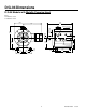
D/G-04 Dimensions D/G-04 Models with Metallic Pumping Head Brass 304 Stainless Steel 316 Stainless Steel 10.38 (263.7) 9.93 (252.2) 7.01 (178) Outlet D-04: 1/2" NPT G-04: 1/2" BSPT 2.25 (57.2) 1.73 (43.9) Good Key 8.71 (221.2) 0.189 (4.8) 4.97 (126) 0.875 (22.23) 4.250 (107.9) 4.25 (108) Inlet D-04: 1/2" NPT G-04: 1/2" BSPT 0.75 (19.1) 2.25 (57.2) 2.75 (69.9) 2.75 (69.9) 3.35 (85.1) 1.71 (43.4) 0.75 (19.1) 3.52 (89.4) 5.00 (127) 6.
D/G-04 Installation NOTE: The numbers in parentheses are the Reference Numbers on the illustrations in the Parts Manual. Important Precautions Location Adequate Fluid Supply. To avoid cavitation and premature pump failure, be sure that the pump will have an adequate fluid supply and that the inlet line will not be obstructed. See “Inlet Piping”. Locate the pump as close to the supply source as possible. Install it in a lighted clean space where it will be easy to inspect and maintain.
D/G-04 Installation Inlet Piping (Suction Feed) Inlet Piping (Pressure Feed) CAUTION: When pumping at temperatures above 160° F (71° C), use a pressure-feed system. Provide for permanent or temporary installation of a vacuum/ pressure gauge to monitor the inlet vacuum or pressure. Pressure at the pump inlet should not exceed 500 psi (34 bar); if it could get higher, install an inlet pressure regulator. Install draincocks at any low points of the suction line, to permit draining in freezing conditions.
D/G-04 Installation Friction Losses Discharge Piping Calculating Friction Losses in Suction Piping NOTE: Consult the Factory before manifolding two or more pumps together. When following the above recommendations (under “inlet Piping”) for minimum hose/pipe I.D. and maximum length, frictional losses in the suction piping are negligible (i.e., Hf = 0) if you are pumping a water-like fluid. NOTE: Single-acting pumps create a pulsing flow.
D/G-04 Installation Before Initial Start-Up Initial Start-Up Procedure Before you start the pump, be sure that: 1. Turn on power to the pump motor. 2. Check the inlet pressure or vacuum. To maintain maximum flow, inlet vacuum must not exceed 7 in. Hg at 70° F (180 mm Hg at 21° C). Inlet pressure must not exceed 500 psi (34 bar). 3. Listen for any erratic noise, and look for unsteady flow. If the pump does not clear, refer to the Trouble-shooting Section. 4.
D/G-04 Maintenance NOTE: The numbers in parentheses are the Ref. Nos. on the illustrations in the Parts Manual. Shutdown Procedure During Freezing Temperatures Daily Take all safety precautions to assure safe handling of the fluid being pumped. Provide adequate catch basins for fluid drainage and use appropriate plumbing from drain ports, etc., when flushing the pump and system with a compatible antifreeze. Check the oil level and the condition of the oil. The oil level should be 1/4 in.
D/G-04 Service (Fluid End) Bolt Torque Specifications Ref. No.
D/G-04 Service (Fluid End) NOTE: The number in parentheses are the Reference numbers on the illustration at right and in the Parts Manual. 2. Inspect Valves (5-11) The three inlet and three outlet valve assemblies are identical (but face in opposite directions). Inspect each valve as follows: a. Check the spring retainer (10), and replace if worn. b. Check the valve spring (8). If shorter than a new spring, replace it (do not stretch a used spring). c. Check the valve (7). If worn excessively, replace it.
D/G-04 Service (Fluid End) 3. Inspect and Replace Diaphragms (17) 4. Flush Contaminant from Hydraulic End a. Lift a diaphragm by one edge, and turn the pump shaft until the diaphragm moves up to “top dead center”. This will expose machined cross-holes in the plunger shaft behind the diaphragm. b. Insert the plunger holder tool through one of the machined cross-holes, to hold the diaphragm up. (Don’t remove the tool until the new diaphragm is installed in step “f” below.) c. Unscrew the diaphragm.
D/G-04 Service (Fluid End) 6. Reinstall Valve Plate (12) and Manifold (3) a. Reinstall the valve plate (12), with the valve assemblies installed as outlined above, onto the diaphragm plate (18) and alignment pins (29). Tighten the two socket-head capscrews evenly and snugly to compress the outer diaphragm beads and hold the valve plate in place. b. Reinstall the O-rings (4) on the front side of the valve plate. Use petroleum jelly or lubricating gel to hold them in place. c.
D/G-04 Service (Hydraulic End) 14 D04-991-2400 5/1/04
D/G-04 Service (Hydraulic End) NOTE: The numbers in parentheses are the Ref. Nos. on the illustrations in the Parts Manual. 2. Reassemble Pistons a. Tip the pump so the pistons are vertical. b. Drop a ball (21) into the opening in the bottom of the piston. c. Insert the valve plunger (24) into a valve cylinder (22). Slide a spring (25) over the plunger, inside the valve cylinder. d. Slide the assembled valve cylinder, plunger, and spring (22-25) into the piston (20). e.
D/G-04 Service (Hydraulic End) 3. Replace Shaft Seal 5. Reinstall Diaphragms NOTE: Inspect the shaft seal (54) before continuing. If it looks damaged in any way, replace it. a. Press the back bearing (55) and seal (54) out of the cover (52). Discard the seal. b. Apply a coating of Loctite High-Performance Pipe Sealant with Teflon ©, or a comparable product, to the outer surface of a new seal and the inside surface of the opening in the back cover (52) where the seal will rest. c.
D/G-04 Troubleshooting Cavitation Pump Runs Rough • • • • • • • • • Inadequate fluid supply because: — Inlet line collapsed or clogged — Clogged line strainer — Inlet line too small or too long — Air leak in inlet line — Worn or damaged inlet hose — Suction line too long — Too many valves and elbows in inlet line Fluid too hot for inlet suction piping system. Air entrained in fluid piping system. Aeration and turbulence in supply tank. Inlet vacuum too high (refer to “Inlet Calculations”, page 3).
D/G-04 Troubleshooting Valve Wear • • • • • Normal wear from high-speed operation Cavitation Abrasives in the fluid Valve incompatible with corrosives in the fluid Pump running too fast Loss of Oil • • • • • • • External seepage Rupture of diaphragm Frozen pump Worn shaft seal Oil drain piping or fill cap loose.
Limited Warranty Wanner Engineering, Inc. extends to the original purchaser of equipment manufacturerd by it and bearing its name, a limited one-year warranty from the date of purchase against defects in material or workmanship, provided that the equipment is installed and operated in accordance with the recommendations and instructions of Wanner Engineering, Inc. Wanner Engineering, Inc.
WANNER ENGINEERING, INC. 1204 Chestnut Avenue, Minneapolis, MN 55403 TEL: (612) 332-5681 FAX: (612) 332-6937 TOLL-FREE FAX [US only]: (800) 332-6812 www.hydra-cell.com email: sales@wannereng.com ©2004 Wanner Engineering, Inc.