HP ENVY m6 Notebook PC Maintenance and Service Guide
© Copyright 2014 Hewlett-Packard Development Company, L.P. AMD, the AMD Arrow logo, and combinations thereof, are trademarks of Advanced Micro Devices, Inc. Bluetooth is a trademark owned by its proprietor and used by Hewlett-Packard Company under license. Microsoft and Windows are U.S. registered trademarks of Microsoft Corporation. SD Logo is a trademark of its proprietor. The information contained herein is subject to change without notice.
Safety warning notice WARNING! To reduce the possibility of heat-related injuries or of overheating the device, do not place the device directly on your lap or obstruct the device air vents. Use the device only on a hard, flat surface. Do not allow another hard surface, such as an adjoining optional printer, or a soft surface, such as pillows or rugs or clothing, to block airflow. Also, do not allow the AC adapter to contact the skin or a soft surface, such as pillows or rugs or clothing, during operation.
iv Safety warning notice
Table of contents 1 Product description ....................................................................................................................................... 1 2 External component identification ................................................................................................................. 4 Finding your hardware and software information ................................................................................................ 4 Locating hardware ..................
5 Removal and replacement procedures for Customer Self-Repair parts ............................................................. 28 Component replacement procedures ................................................................................................................. 28 Battery ............................................................................................................................................... 29 WLAN module ..............................................................
Restore and recovery .......................................................................................................................................... 69 Recovering using HP Recovery Manager .......................................................................................... 70 What you need to know before you get started ............................................................ 70 Using the HP Recovery partition (select models only) ..................................................
viii
1 Product description Category Description Product Name HP ENVY m6 Notebook PC Processors AMD™ A10-5750M 2.50-GHz processor (turbo up to 3.50-GHz; 1600-MHz FSB, 4.0-MB L2 cache, 1600-MHz DDR3, quad core, 35 W) AMD A10-7300 2.0-GHz processor (turbo up to 3.20-GHz; soldered on chip (SOC), 4.0-MB L2 cache, quad core, 19 W) AMD FX-7500 2.1-GHz processor (turbo up to 3.30-GHz; soldered on chip (SOC), 4.
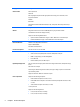
Category Description Audio and video Stereo speakers (2) Subwoofer Dual array digital microphones with appropriate beam-forming, echo-cancellation, noisesuppression software HD Audio Beats Audio Integrated HP TrueVision HD webcam (fixed [no tilt], activity LED, 1280×720 by 30 frames per second) Ethernet Integrated 10/100/1000 network interface card (NIC) Wireless Integrated wireless local area network (WLAN) options by way of wireless module Two WLAN antennas built into display assembly Support for t
Category Description Security Support for the following: Operating system ● Security cable lock ● Trusted Platform Module (TPM) ● HP SimplePass support Preinstalled: Microsoft Windows 8.1 Standard Microsoft Windows 8.
2 External component identification Finding your hardware and software information Locating hardware To find out what hardware is installed on your computer: 1. From the Start screen, type control panel, and then select Control Panel. 2. Select System and Security, select System, and then click Device Manager in the left column. A list reveals all the devices installed in your computer. To find out information about system hardware components and the system BIOS version number, press fn +esc.
Display Component Description (1) Turns off the display and initiates Sleep if the display is closed while the power is on. Internal display switch NOTE: The internal display switch is not visible from the outside of the computer. (2) Internal microphones Record sound. (3) Webcam light On: The webcam is in use. (4) Webcam Records video and captures photographs. Some models allow you to video conference and chat online using streaming video.
Top TouchPad Component Description (1) Left control zone Textured area that allows you to perform additional gestures. (2) TouchPad zone Reads your finger gestures to move the pointer or activate items on the screen. NOTE: 6 The TouchPad also supports edge-swipe gestures. (3) Left TouchPad button Functions like the left button on an external mouse. (4) Right TouchPad button Functions like the right button on an external mouse.
Lights Component (1) (2) (3) Description Power light Mute light Wireless light ● On: The computer is on. ● Blinking: The computer is in the Sleep state, a powersaving state. The computer shuts off power to the display and other unneeded components. ● Off: The computer is off or in Hibernation. Hibernation is a power-saving state that uses the least amount of power. ● Amber: Computer sound is off. ● Off: Computer sound is on.
Buttons, speakers, and fingerprint reader (select models only) Component (1) Description Power button ● When the computer is off, press the button to turn on the computer. ● When the computer is on, press the button briefly to initiate Sleep. ● When the computer is in the Sleep state, press the button briefly to exit Sleep. ● When the computer is in Hibernation, press the button briefly to exit Hibernation.
Keys Component Description (1) esc key Displays system information when pressed in combination with the fn key. (2) fn key Executes frequently used system functions when pressed in combination with the esc key or, on select models, the b key or the spacebar. (3) Windows key Returns you to the Start screen from an open app or the Windows desktop. NOTE: Pressing the Windows key again will return you to the previous screen. (4) Action keys Execute frequently used system functions.
NOTE: The action key feature is enabled at the factory. You can disable this feature in Setup Utility (BIOS). Refer to Help and Support for additional information. After you have disabled the action key feature, you can still perform each function by pressing the fn key in combination with the appropriate action key. Icon Description Opens Help and Support, which provides tutorials, information about the Windows operating system and your computer, answers to questions, and updates to your computer.
Left side Component (1) Description Security cable slot Attaches an optional security cable to the computer. NOTE: The security cable is designed to act as a deterrent, but it may not prevent the computer from being mishandled or stolen. (2) Vent Enables airflow to cool internal components. NOTE: The computer fan starts up automatically to cool internal components and prevent overheating. It is normal for the internal fan to cycle on and off during routine operation.
Component Description ● Off: The computer is off or in Hibernation. Hibernation is a power-saving state that uses the least amount of power. Right side Component (1) Description Audio-out (headphone)/Audio-in (microphone) jack Connects optional powered stereo speakers, headphones, earbuds, a headset, or a television audio cable. Also connects an optional headset microphone. This jack does not support optional microphone-only devices.
Component (5) Description Power connector ● Amber: The computer is connected to external power and the battery is charged from 0 to 90 percent. ● Blinking amber: A battery that is the only available power source has reached a low battery level. When the battery reaches a critical battery level, the battery light begins blinking rapidly. ● Off: The battery is fully charged. Connects an AC adapter.
Component (3) Description Vents (4) Enable airflow to cool internal components. NOTE: The computer fan starts up automatically to cool internal components and prevent overheating. It is normal for the internal fan to cycle on and off during routine operation. (4) Battery release latch Releases the battery. (5) HP Triple Bass Reflex Subwoofer Provides superior bass sound.
3 Illustrated parts catalog NOTE: HP continually improves and changes product parts. For complete and current information on supported parts for your computer, go to http://partsurfer.hp.com, select your country or region, and then follow the on-screen instructions.
Item Component (1) Display assembly (includes webcam/microphone module and wireless antenna cables): (2) 15.6-in, AntiGlare, FHD, LED, TouchScreen display assembly for use on all computer models 788475-001 15.
Item Component Spare part number For use only with system boards with spare part numbers 760043-601, 760043-501, 760043-001, 782279-601, 782279-501, and 782279-001. 764034-001 For use only with system boards with spare part numbers 760042-501 and 760042-001.
Miscellaneous parts Component Spare part number AC adapter: 45-W HP Smart AC adapter for use only on computer models equipped with an AMD processor (non-PFC, RC, 4.5-mm) 741727-001 65-W HP Smart AC adapter (non-PFC, 4.5-mm) for use on all computer models 710412-001 HDMI-to-VGA adapter 701943-001 Power cord (3-pin, black, 1.
Mass storage devices Item Component Spare part number (1) External USB DVD±RW Double-Layer with SuperMulti Drive 747080-001 (2) Hard drive (does not include hard drive bracket or hard drive connector cable): 1.5-TB, 5400-rpm, 9.5-mm 747375-001 1.0-TB, 5400-rpm, 9.5-mm 778192-001 750-GB, 5400-rpm, 9.5-mm 652012-001 750-GB, 5400-rpm, 9.
Sequential part number listing Spare part number Description 651948-001 RTC battery 652012-001 750-GB, 5400-rpm, SATA, 9.5-mm hard drive for use on all computer models (does not include hard drive bracket or hard drive connector cable) NOTE: The hard drive bracket and screws are included in the Hard Drive Hardware Kit, spare part number 720545-001.
Spare part number Description 741727-001 45-W HP Smart AC adapter for use only on computer models equipped with an AMD processor (non-PFC, RC, 4.5-mm) 747080-001 External USB DVD±RW Double-Layer with SuperMulti Drive 747375-001 1.5-TB, 5400-rpm, SATA, 9.5-mm hard drive for use on all computer models (does not include hard drive bracket or hard drive connector cable) NOTE: The hard drive bracket and screws are included in the Hard Drive Hardware Kit, spare part number 720545-001.
22 Spare part number Description 782279-001 System board equipped with an AMD FX-7500 2.1-GHz processor (turbo up to 3.30-GHz; SOC, 4.0-MB L2 cache, quad core, 19 W) and a non-Windows 8 operating system (includes replacement thermal material) 782279-501 System board equipped with an AMD FX-7500 2.1-GHz processor (turbo up to 3.30-GHz; SOC, 4.
4 Removal and replacement procedures preliminary requirements Tools required You will need the following tools to complete the removal and replacement procedures: ● Flat-bladed screw driver ● Magnetic screw driver ● Phillips P0 and P1 screw drivers Service considerations The following sections include some of the considerations that you must keep in mind during disassembly and assembly procedures.
Cables and connectors CAUTION: When servicing the computer, be sure that cables are placed in their proper locations during the reassembly process. Improper cable placement can damage the computer. Cables must be handled with extreme care to avoid damage. Apply only the tension required to unseat or seat the cables during removal and insertion. Handle cables by the connector whenever possible. In all cases, avoid bending, twisting, or tearing cables.
CAUTION: To prevent damage to the computer when you are removing or installing internal components, observe these precautions: Keep components in their electrostatic-safe containers until you are ready to install them. Before touching an electronic component, discharge static electricity by using the guidelines described in this section. Avoid touching pins, leads, and circuitry. Handle electronic components as little as possible. If you remove a component, place it in an electrostatic-safe container.
Packaging and transporting guidelines Follow these grounding guidelines when packaging and transporting equipment: ● To avoid hand contact, transport products in static-safe tubes, bags, or boxes. ● Protect ESD-sensitive parts and assemblies with conductive or approved containers or packaging. ● Keep ESD-sensitive parts in their containers until the parts arrive at static-free workstations. ● Place items on a grounded surface before removing items from their containers.
Equipment guidelines Grounding equipment must include either a wrist strap or a foot strap at a grounded workstation. ● When seated, wear a wrist strap connected to a grounded system. Wrist straps are flexible straps with a minimum of one megohm ±10% resistance in the ground cords. To provide proper ground, wear a strap snugly against the skin at all times. On grounded mats with banana-plug connectors, use alligator clips to connect a wrist strap.
5 Removal and replacement procedures for Customer Self-Repair parts NOTE: The Customer Self-Repair program is not available in all locations. Installing a part not supported by the Customer Self-Repair program may void your warranty. Check your warranty to determine if Customer Self-Repair is supported in your location. NOTE: HP continually improves and changes product parts. For complete and current information on supported parts for your computer, go to http://partsurfer.hp.
Battery Description Spare part number 6-cell, 62-Wh, 2.80-Ah, Li-ion battery 710417-001 6-cell, 47-Wh, 2.20-Ah, Li-ion battery 710416-001 Before removing the battery, follow these steps: 1. Turn off the computer. If you are unsure whether the computer is off or in Hibernation, turn the computer on, and then shut it down through the operating system. 2. Disconnect the power from the computer by unplugging the power cord from the computer. 3. Disconnect all external devices from the computer.
WLAN module Description Spare part number Qualcomm Atheros AR9565 802.11b/g/n 1×1 WiFi + BT 4.0 Combo Adapter 733476-001 CAUTION: To prevent an unresponsive system, replace the wireless module only with a wireless module authorized for use in the computer by the governmental agency that regulates wireless devices in your country or region. If you replace the module and then receive a warning message, remove the module to restore device functionality, and then contact technical support.
NOTE: The WLAN antenna cable labeled “1” connects to the WLAN module “Main” terminal labeled “1”. The WLAN antenna cable labeled “2” connects to the WLAN module “Aux” terminal labeled “2”. 7. Remove the Phillips PM2.0×2.5 screw (2) that secures the WLAN module to the system board. (The WLAN module tilts up.) 8. Remove the WLAN module (3) by pulling the module away from the slot at an angle.
Hard drive NOTE: The hard drive spare part kit does not include the hard drive bracket or hard drive connector cable. The hard drive bracket and hard drive connector cable are included in the Hard Drive Hardware Kit, spare part number 720545-001. Description Spare part number 1.5-TB, 5400-rpm, 9.5-mm 747375-001 1.0-TB, 5400-rpm, 9.5-mm 778192-001 750-GB, 5400-rpm, 9.5-mm 652012-001 750-GB, 5400-rpm, 9.5-mm, 8-GB hybrid 732001-001 Before removing the hard drive, follow these steps: 1.
4. If it is necessary to disassemble the hard drive, perform the following steps: a. Position the hard drive with the connector toward you. b. Disconnect the hard drive connector cable (1) from the hard drive. c. Spread the left and right sides (2) of the hard drive bracket outward to separate the bracket from the hard drive. d. Remove the hard drive bracket (3) from the hard drive.
CAUTION: Failure to update the computer to the latest BIOS prior to installing new memory may result in various system problems. To update BIOS: 1. Navigate to www.hp.com. 2. Click Support & Drivers > click Drivers & Software. 3. In the Enter a product name/number box, type the computer model information, and then click Search. 4. Click the link for the computer model. 5. Select the operating system, and then click Next. 6. Under Step 2: Select a Download, click the BIOS link. 7.
2. Spread the retaining tabs (1) on each side of the memory module slot to release the memory module. (The memory module tilts up.) 3. Remove the memory module (2) by pulling the module away from the slot at an angle. Reverse this procedure to install a memory module.
6 Removal and replacement procedures for Authorized Service Provider parts CAUTION: Components described in this chapter should only be accessed by an authorized service provider. Accessing these parts can damage the computer or void the warranty. NOTE: HP continually improves and changes product parts. For complete and current information on supported parts for your computer, go to http://partsurfer.hp.com, select your country or region, and then follow the on-screen instructions.
Reverse this procedure to install the RTC battery. When installing the disc cell RTC battery, make sure the “+” sign faces up.
Base enclosure Description Spare part number Base enclosure; includes red Beats logo 760035-001 Base enclosure; includes grey Beats logo 774152-001 Before removing the base enclosure, follow these steps: 1. Turn off the computer. If you are unsure whether the computer is off or in Hibernation, turn the computer on, and then shut it down through the operating system. 2. Disconnect the power from the computer by unplugging the power cord from the computer. 3.
4. Remove the following screws: (1) Two Phillips PM2.5×5.5 screws under the front edge of the service cover (2) Three Phillips PM2.5×3.0 screws in the hard drive bay (3) Seven Phillips PM1.5×2.0 screws in the battery bay 5. Remove the base enclosure.
Reverse this procedure to install the base enclosure. Display assembly Description Spare part number 15.6-in, AntiGlare, FHD, LED, TouchScreen display assembly for use on all computer models 788475-001 15.6-in, AntiGlare, HD, LED, TouchScreen display assembly for use on all computer models 788474-001 To remove the display assembly and access the display assembly subcomponents, follow these steps: 1. Turn off the computer.
6. Remove the three Phillips PM2.5×4.5 screws (1) (two on the left hinge, one on the right hinge) that secure the display assembly to the top cover. 7. Remove the Phillips PM2.5×6.5 screw (2) on the right hinge that secures the display assembly to the top cover. 8. Open the display hinges (1) as far as they will open.
9. Remove the display assembly (2) from the computer. Reverse this procedure to install the display assembly. Fan Description Spare part number Fan (includes cable) 720235-001 Before removing the fan, follow these steps: 1. Turn off the computer. If you are unsure whether the computer is off or in Hibernation, turn the computer on, and then shut it down through the operating system. 2. Disconnect the power from the computer by unplugging the power cord from the computer. 3.
3. Remove the fan (3). Reverse this procedure to install the fan. System board NOTE: The system board spare part kit includes replacement thermal material. Description Spare part number For use only with an AMD A10-5750M 2.50-GHz processor (spare part number 713548-001); equipped with the Windows 8 Standard operating system 760042-501 For use only with an AMD A10-5750M 2.
Before removing the system board, follow these steps: 1. Turn off the computer. If you are unsure whether the computer is off or in Hibernation, turn the computer on, and then shut it down through the operating system. 2. Disconnect the power from the computer by unplugging the power cord from the computer. 3. Disconnect all external devices from the computer. 4. Remove the battery (see Battery on page 29), and then remove the following components: a. Service cover (see WLAN module on page 30) b.
2.
3. Remove the nine Phillips PM2.0×2.9 screws that secure the system board to the top cover. 4. Lift the left side of the system board (1) until it rests at an angle. 5. Remove the system board (2) by sliding it up and to the left an angle. Reverse this procedure to install the system board.
Heat sink NOTE: The heat sink spare part kit includes replacement thermal material. Description Spare part number For use only with system boards with spare part numbers 760043-601, 760043-501, 760043-001, 782279-601, 782279-501 and 782279-001. 764034-001 For use only with system boards with spare part numbers 760042-501 and 760042-001. 720539-001 Before removing the heat sink, follow these steps: 1. Turn off the computer.
3. Remove the heat sink (2). NOTE: Due to the adhesive quality of the thermal material located between the heat sink and the system board components, it may be necessary to move the heat sink from side to side to detach it. NOTE: The thermal material must be thoroughly cleaned from the surfaces of the heat sink and the system board components each time the heat sink is removed. Replacement thermal material is included with the heat sink, processor, and system board spare part kits.
Reverse this procedure to install the heat sink. Processor NOTE: The processor spare part kit includes replacement thermal material. Description Spare part number AMD A10-5750M 2.50-GHz processor (turbo up to 3.50-GHz; 1600-MHz FSB, 4.0- MB L2 cache, DDR3, quad core, 35 W) 713548-001 NOTE: This processor is intended only for use with system boards with spare part numbers 760042-501 and 760042-001. Before removing the processor, follow these steps: 1. Turn off the computer.
d. Display assembly (see Display assembly on page 40) e. Fan (see Fan on page 42) f. System board (see System board on page 43) g. Heat sink (see Heat sink on page 47) Remove the processor: 1. Use a flat-bladed screw driver (1) to turn the processor locking screw one-half turn counterclockwise (2), until you hear a click. 2. Lift the processor (3) straight up, and remove it.
Connector board NOTE: The connector board spare part kit includes the audio jack, RJ-45 jack, USB port, and 2 cables. Description Spare part number Connector board 760038-001 Before removing the connector board, follow these steps: 1. Turn off the computer. If you are unsure whether the computer is off or in Hibernation, turn the computer on, and then shut it down through the operating system. 2. Disconnect the power from the computer by unplugging the power cord from the computer. 3.
6. Lift the right side of the connector board (2) until it rests at an angle. 7. Remove the connector board (3) by sliding it up and to the right at an angle. Reverse this procedure to install the connector board. Power connector cable Description Spare part number Power connector cable 720537-001 Before removing the power connector cable, follow these steps: 1. Turn off the computer.
3. Release the power connector (3) from the clips and mold built into the top cover. 4. Remove the power connector cable. Reverse this procedure to install the power connector cable. Subwoofer Description Spare part number Subwoofer (includes cable and 3 isolators) 720563-001 Before removing the subwoofer, follow these steps: 1. Turn off the computer. If you are unsure whether the computer is off or in Hibernation, turn the computer on, and then shut it down through the operating system. 2.
3. Remove the subwoofer (3). NOTE: The subwoofer includes three rubber isolators (4). These isolators are crucial to the performance of the subwoofer. Reverse this procedure to install the subwoofer.
Speakers Description Spare part number Speakers (include left and right speakers, 2 cables, and 4 isolators) 720561-001 Before removing the speakers, follow these steps: 1. Turn off the computer. If you are unsure whether the computer is off or in Hibernation, turn the computer on, and then shut it down through the operating system. 2. Disconnect the power from the computer by unplugging the power cord from the computer. 3. Disconnect all external devices from the computer. 4.
4. Remove the speakers (4). NOTE: The speakers includes four rubber isolators (5). These isolators are crucial to the performance of the speakers. Reverse this procedure to install the speakers.
TouchPad assembly Description Spare part number TouchPad assembly (includes TouchPad bracket, TouchPad button board, TouchPad, and cables) 760041-001 Before removing the TouchPad, follow these steps: 1. Turn off the computer. If you are unsure whether the computer is off or in Hibernation, turn the computer on, and then shut it down through the operating system. 2. Disconnect the power from the computer by unplugging the power cord from the computer. 3.
5. Lift the rear edge of the TouchPad (3) until it rests at an angle. 6. Slide the TouchPad (4) toward the back of the top cover, and then lift the TouchPad straight up and remove it. Reverse this procedure to install the TouchPad.
Power button board Description Spare part number Power button board (includes cable) 720553-001 Before removing the power button board, follow these steps: 1. Turn off the computer. If you are unsure whether the computer is off or in Hibernation, turn the computer on, and then shut it down through the operating system. 2. Disconnect the power from the computer by unplugging the power cord from the computer. 3. Disconnect all external devices from the computer. 4.
Keyboard NOTE: The keyboard spare part kit includes a keyboard cable. For use in country/region Spare part number Keyboard in natural silver finish with backlight (includes keyboard cable and backlight cable): For use in Canada 760743-DB1 For use in the United States 760743-001 Before removing the keyboard, follow these steps: 1. Turn off the computer. If you are unsure whether the computer is off or in Hibernation, turn the computer on, and then shut it down through the operating system. 2.
3. Remove the keyboard shield (3). CAUTION: When removing the keyboard shield, make sure the keyboard cable and backlight cable are not damaged when being released through the opening in the keyboard shield. The keyboard shield is available using spare part number 734817-001. 4. Partially open the computer. 5. Insert a thin tool into the keyboard release hole in the memory module compartment, and then press on the back of the keyboard until the keyboard disengages from the computer. 6.
9. Remove the keyboard (3). Reverse this procedure to install the keyboard.
7 Using Setup Utility (BIOS) Setup Utility, or Basic Input/Output System (BIOS), controls communication between all the input and output devices on the system (such as disk drives, display, keyboard, mouse, and printer). Setup Utility (BIOS) includes settings for the types of devices installed, the startup sequence of the computer, and the amount of system and extended memory. Starting Setup Utility (BIOS) CAUTION: Use extreme care when making changes in Setup Utility (BIOS).
Downloading a BIOS update CAUTION: To reduce the risk of damage to the computer or an unsuccessful installation, download and install a BIOS update only when the computer is connected to reliable external power using the AC adapter. Do not download or install a BIOS update while the computer is running on battery power, docked in an optional docking device, or connected to an optional power source.
8 Using HP PC Hardware Diagnostics (UEFI) HP PC Hardware Diagnostics is a Unified Extensible Firmware Interface (UEFI) that allows you to run diagnostic tests to determine whether the computer hardware is functioning properly. The tool runs outside the operating system so that it can isolate hardware failures from issues that are caused by the operating system or other software components. To start HP PC Hardware Diagnostics (UEFI): 1. Start Setup Utility: ● Computers or tablets with keyboards: ▲ 2.
3. In the text box, enter the product name, and then click Go. – or – Click Find Now to let HP automatically detect your product. 4. Select your computer model, and then select your operating system. 5. In the Diagnostic section, click HP UEFI Support Environment. – or – Click Download, and then select Run.
9 Specifications Computer specifications Metric U.S. Width 37.95 cm 14.94 in Depth 25.07 cm 9.87 in Height (front to rear) 1.89 to 2.99 cm 0.74 to 1.18 in Weight 2.76 kg 6.08 lbs Dimensions HP ENVY TouchSmart 15 Notebook PC Input power Operating voltage and current 19.5 V dc @ 3.33 A – 65 W 19.5 V dc @ 4.62 A – 90 W 19.5 V dc @ 6.
10 Backing up, restoring, and recovering This chapter provides information about the following processes. The information in the chapter is standard procedure for most models. ● Creating recovery media and backups ● Restoring and recovering your system For additional information, refer to the HP Support Assistant. ▲ From the Start screen, type support, and then select the HP Support Assistant app.
● Only one set of recovery media can be created. Handle these recovery tools carefully, and keep them in a safe place. ● HP Recovery Manager examines the computer and determines the required storage capacity for the media that will be required. ● To create recovery discs, your computer must have an optical drive with DVD writer capability, and you must use only high-quality blank DVD-R, DVD+R, DVD-R DL, or DVD+R DL discs.
IMPORTANT: Not all methods are available on all models. ● Windows offers several options for restoring from backup, refreshing the computer, and resetting the computer to its original state. For more information see Help and Support. ▲ From the Start screen, type support, and then select the HP Support Assistant app. - or From the Windows desktop, click the question mark icon in the notification area, at the far right of the taskbar.
● To use the Factory Reset option (select models only), you must use HP Recovery media. If you have not already created recovery media, see Creating HP Recovery media (select models only) on page 68. ● If your computer does not allow the creation of HP Recovery media or if the HP Recovery media does not work, you can obtain recovery media for your system from support. See the Worldwide Telephone Numbers booklet included with the computer. You can also find contact information from the HP website.
1. If possible, back up all personal files. 2. Insert the HP Recovery media, and then restart the computer. NOTE: If the computer does not automatically restart in HP Recovery Manager, change the computer boot order. See Changing the computer boot order on page 72. 3. Follow the on-screen instructions.
11 Power cord set requirements The wide-range input feature of the computer permits it to operate from any line voltage from 100 to 120 volts AC, or from 220 to 240 volts AC. The 3-conductor power cord set included with the computer meets the requirements for use in the country or region where the equipment is purchased. Power cord sets for use in other countries and regions must meet the requirements of the country or region where the computer is used.
74 Country/region Accredited agency Applicable note number Sweden SEMKO 1 Switzerland SEV 1 Taiwan BSMI 4 The United Kingdom BSI 1 The United States UL 2 1. The flexible cord must be Type HO5VV-F, 3-conductor, 1.0-mm² conductor size. Power cord set fittings (appliance coupler and wall plug) must bear the certification mark of the agency responsible for evaluation in the country or region where it will be used. 2. The flexible cord must be Type SPT-3 or equivalent, No.
12 Recycling When a non-rechargeable or rechargeable battery has reached the end of its useful life, do not dispose of the battery in general household waste. Follow the local laws and regulations in your area for battery disposal. HP encourages customers to recycle used electronic hardware, HP original print cartridges, and rechargeable batteries. For more information about recycling programs, see the HP Web site at http://www.hp.com/ recycle.
Index A AC adapter 12 AC adapter, spare part numbers 18, 20, 21 action keys 9 identifying 9 audio, product description 2 audio-out (headphone)/audio-in (microphone) jack 12 B backups 68 base enclosure removal 38 spare part numbers 17, 21, 38 battery removal 29 spare part numbers 17, 20, 29 battery cover, identifying 13 battery release latch 14 BIOS determining version 63 downloading an update 64 starting the Setup Utility 63 updating 63 boot order changing 72 buttons left TouchPad 6 power 8 right TouchPad 6
J jacks audio-out (headphone)/audio-in (microphone) 12 network 12 RJ-45 (network) 12 K keyboard product description 2 removal 60 spare part numbers 16, 21, 60 keyboard shield removal 60 spare part number 16, 20, 61 keys action 9 esc 9 fn 9 Windows 9 L latch, battery release 14 left control zone, identifying 6 lights AC adapter 12 caps lock 7 fingerprint reader 7 hard drive 11 mute 7 power 7, 11 RJ-45 (network) status 12 wireless 7 M mass storage device illustrated 19 precautions 24 spare part numbers 19 mem
S Screw Kit, spare part number 18, 20 security cable slot, identifying 11 security, product description 3 service considerations cables 24 connectors 24 plastic parts 23 service cover removal 30 spare part number 17, 20, 30 service tag 14 serviceability, product description 3 slots memory card reader 11 security cable 11 speakers identifying 8 removal 53, 55 spare part numbers 16, 17, 20, 53, 55 specifications 67 subwoofer removal 53 spare part number 17, 20, 53 supported discs, recovery 69 system board rem