WEBPAM USER MANUAL Version 1.
WebPAM User Manual Copyright © 2005 Promise Technology, Inc. All Rights Reserved. Copyright by Promise Technology, Inc. (Promise Technology). No part of this manual may be reproduced or transmitted in any form without the expressed, written permission of Promise Technology. Trademarks Promise, and the Promise logo are registered in U.S. Patent and Trademark Office. All other product names mentioned herein may be trademarks or registered trademarks of their respective companies.
Contents Chapter 1: Introduction . . . . . . . . . . . . . . . . . . . . . . . . . . . . . . . . . . . . .1 WebPAM Components . . . . . . . . . . . . . . . . . . . . . . . . . . . . . . . . . . .2 How They Work Together . . . . . . . . . . . . . . . . . . . . . . . . . . . . . . . . .2 PAM Installation Options . . . . . . . . . . . . . . . . . . . . . . . . . . . . . . . . . .3 About This Manual . . . . . . . . . . . . . . . . . . . . . . . . . . . . . . . . . . . . . . .5 Chapter 2: Installation . . . . .
WebPAM User Manual Chapter 5: Monitor and Manage . . . . . . . . . . . . . . . . . . . . . . . . . . . . .35 Log-in to WebPAM . . . . . . . . . . . . . . . . . . . . . . . . . . . . . . . . . . . . .35 Regular Connection . . . . . . . . . . . . . . . . . . . . . . . . . . . . . . . . .35 Secure Connection . . . . . . . . . . . . . . . . . . . . . . . . . . . . . . . . . .35 Log-out of WebPAM . . . . . . . . . . . . . . . . . . . . . . . . . . . . . . . . . . . .36 User Management . . . . . . . . . . . . .
Contents Chapter 5: Monitor and Manage, continued Logical Drives . . . . . . . . . . . . . . . . . . . . . . . . . . . . . . . . . . . . . . . . .62 Logical Drive View . . . . . . . . . . . . . . . . . . . . . . . . . . . . . . . . . .62 Create a Logical Drive . . . . . . . . . . . . . . . . . . . . . . . . . . . . . . .62 JBOD . . . . . . . . . . . . . . . . . . . . . . . . . . . . . . . . . . . . . . . . . . . .65 Delete a Logical Drive . . . . . . . . . . . . . . . . . . . . . . . . . . . . . . . .
WebPAM User Manual Chapter 6: Technology Background . . . . . . . . . . . . . . . . . . . . . . . . .89 Introduction to RAID . . . . . . . . . . . . . . . . . . . . . . . . . . . . . . . . . . . .89 RAID 0 – Stripe . . . . . . . . . . . . . . . . . . . . . . . . . . . . . . . . . . . . .90 RAID 1 – Mirror . . . . . . . . . . . . . . . . . . . . . . . . . . . . . . . . . . . . .91 RAID 5 – Block Striping with Distributed Parity . . . . . . . . . . . . .92 RAID 10 – Mirror / Stripe . . . . . . . . . . . . .
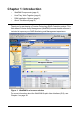
Chapter 1: Introduction • WebPAM Components (page 2) • How They Work Together (page 2) • PAM Installation Options (page 3) • About This Manual (page 5) Thank you for purchasing a Promise Technology RAID Controller product. This Web-based Promise Array Management (WebPAM) browser-based software is included to improve your RAID Monitoring and Management experience. Figure 1. WebPAM in a browser window For more information about the WebPAM Graphic User Interface (GUI), see Chapter 4 on page 29.
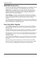
WebPAM User Manual WebPAM Components There are two components to WebPAM. Depending on your installation, all three may be on the same workstation or work separately across your network: Utility Server – The Utility Server runs on the “Host PC”. The Utility Server software monitors and reports on the condition of the RAID logical drives and provides a complete set of management tools. It displays a Graphic User Interface (GUI) on your Internet Browser.
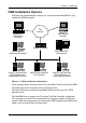
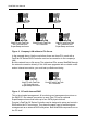
Chapter 1: Introduction PAM Installation Options Following are some examples of ways you can incorporate WebPAM into your network and RAID systems. The Internet Desktop PC with Internet browser Laptop PC with Internet browser Router & Firewall File Server with Utility Server Networked PC with Internet browser Host PC with FastTrak SX Controller and SuperSwap enclosure Host PC with FastTrak SX Controller Host PC with FastTrak SX Controller and SuperSwap enclosure Figure 1.
WebPAM User Manual Networked PC Networked PC Host PC with FastTrak SX Controller and SuperSwap enclosure Host PC with FastTrak SX Controller Host PC with FastTrak SX Controller and SuperSwap enclosure Figure 2. Company LAN without a File Server In the example above, like the one before, there are three PCs, each with a FastTrak SX Series RAID Controller card and a connection to the company’s LAN. But this network has no file server.
Chapter 1: Introduction About This Manual This User Manual describes how to setup, use and maintain the Web-based Promise Array Management (WebPAM) software. This manual includes a full table of contents, chapter task lists and numerous cross-references to help you find the specific information you are looking for. Also included are four levels of notices: Note A Note provides helpful information such as hints or alternative ways of doing a task.
WebPAM User Manual 6
Chapter 2: Installation • Utility Server (below) • Java Runtime Environment (page 8) • Operating System Support (page 8) • Before You Start... (page 8) • Install WebPAM (page 9) WebPAM installation software will install two major components: • Utility Server – WebPAM RAID monitoring and Networking software • Java Runtime Environment (if not previously installed) Utility Server The Utility Server installs on the PC with the FastTrak RAID Controller card (the “Host PC”).
WebPAM User Manual Java Runtime Environment If you are planning to use other applications that rely on JRE or JDK, always install them first before you install WebPAM. WebPAM will use the existing JRE rather than installing a second one. WebPAM will install JRE 1.4 on your system unless you already have JRE or JDK versions 1.3.0 or 1.4.
Chapter 2: Installation Install WebPAM Follow these steps to install WebPAM on your Windows-based PC or Server. 1. Boot the PC/server and launch Windows. If the computer is already running, exit all programs. 2. Insert the software CD into your CD-ROM drive. 3. Double-click on the Install CD's icon to open it. 4. Double-click on the Installer icon to launch it (right). The first WebPAM installation dialog box appears, as shown on the next page. 5.
WebPAM User Manual 6. When the License Agreement appears (above), click the “I accept the terms of the license agreement” radio button. Then click the Next button.
Chapter 2: Installation 7. When the Choose Install Folder screen appears (above), make your selection of a folder for the WebPAM applications you are installing. The default folder is C:\Program Files\Promise\WebPAM 2.0. If you want a different folder, type its location and click the Browse button. If you change your mind and want the default location, click on the Back button, then the Next button. Click the Next button when you are finished.
WebPAM User Manual 8. When the SSL Security Options screen appears (above), you can check External Security. An explanation follows. External SSL Security – Applies security to all connections involving the Internet or outside your company firewall. Security options are invisible to authorized users. Promise Technology provides a default certificate for the server as well as for internal data communication.
Chapter 2: Installation 9. When the Installation Summary screen appears (above), review your choices. To make changes, click the Back button. To continue, click the Finish button.
WebPAM User Manual 10. When the Install Complete screen appears (above), the installation process is finished. Click the Finish button.
Chapter 2: Installation 11. When the Install Complete screen appears (above), the installation process is finished. Click the Finish button to go to the Promise Registration website. Important Registration of your VTrak and WebPAM provides useful information that helps Promise Technologies to offer better products and support. Please take a few minutes to register. Thanks! This completes the WebPAM installation. Go to Chapter 3: Setup (page 17).
WebPAM User Manual 16
Chapter 3: Setup • Log-in to WebPAM (page 17) • Access a Host PC (page 19) • Recommended Initial Settings (page 20) • Delete the Temporary Logical Drive (page 22) • Create a New Logical Drive (page 23) • Log-out of WebPAM (page 27) • Internet Connection using WebPAM (page 27) • Run WebPAM without Network Connection (page 27) After installation, the next step is to log into and configure WebPAM PRO. Log-in to WebPAM Double-click on the WebPAM icon on your desktop (right). Or, 1.
WebPAM User Manual https://127.0.0.1:8443/promise Note that the IP address shown above applies to a log-in at the Host PC. When you log in over a network, you will enter the Host PC’s actual IP address. 3. When the opening screen appears, type admin in the Login ID field. Type admin again in the Password field. The WebPAM login and password are case sensitive. 4. Click the Sign in button.
Chapter 3: Setup After sign-in, the WebPAM opening screen appears. Access a Host PC WebPAM includes a navigation tree or Tree View in the left frame of the broswer window. Click on the + icons to expand the tree.
WebPAM User Manual A detailed discussion of WebPAM graphic user interface is found in Chapter 4 on page 29. Recommended Initial Settings These settings are recommended and now is the best time to make them. You can change them later as necessary. Administrator’s Settings To make the Admistrator’s password and notification settings: 1. In Tree View, under Administrative Tools, click on the User Management icon. 2. In the Management Window, click on the admin link. 3. Click on the Settings tab.
Chapter 3: Setup 4. If you want to change the default password, type the new password into the New Password field. Use up to 8 letters and numbers but no spaces or other characters. 5. Type the same password into the Retype Password field. 6. If you plan to set up Event Notification, type the Administrator’s email address in the Email field. 7. Click on the Submit button. If the action was successful, the Management Window will display the message “Update Success.” 8.
WebPAM User Manual Utility Configuration If you plan to set up Event Notification, you must make these settings. 1. In Tree View, under Administrative Tools, click on the Utilility Configuration icon. 2. Enter the Sender’s address in the Email Sender field. Be sure the sender has an account in your email system. See your IT admininstrator. 3. Enter your email server in the Email Server field. 4. Keep or change the Email Subject line. 5. Click the Submit button when you are done.
Chapter 3: Setup 2. Click on the Logical Drive View icon and select the Delete tab. 3. Check the box to the left of the logical drive you want to delete. Logical drives created in FastBuild appear in WebPAM as PROMISE LD x. 4. Click the Submit button. 5. In the Confirmation box, click the OK button. The temporary logical drive is deleted. Create a New Logical Drive A logical drive is a collection of physical drives in a RAID. To create a new logical drive: 1.
WebPAM User Manual 4. Click the Next button. 5. If you want to create a logical drive with unused capacity, enter the assigned (used) capacity in the Logical Drive Size field. To use the maximum capacity, check the Use Maximum Capacity box. 6. Click on the disk drives to select them. Available drives have a black frame. Selected drives have a red frame. 7. Click the Next button. 8. Enter a name for the logical drive in the field provided. 9. Click the Next button.
Chapter 3: Setup 10. Select a Stripe Block Size from the dropdown menu. Choose from 32, 64 or 128 KB. The size selected affects how FastTrak sends and receives data blocks to and from the drives. In general, a larger block size is better when handling large data transfers (such as A/V editing and graphics) while a smaller size is better when handling email and other common server data. The default is 64KB. When in doubt, use the default value. 11. Select a Write Cache policy from the dropdown menu.
WebPAM User Manual The result of the logical drive creation operation are displayed. Click on the Logical Drive logical drive. Icon to see all of the information about your new Before you can use your new logical drive, you must partition and format the logical drive using your PC’s operating system. See “Appendix B: Partition and Format” on page 105 for more information.
Chapter 3: Setup Log-out of WebPAM There are two ways to log out of WebPAM: • Close your browser window • Click Logout on the WebPAM banner (below) After logging out, you must enter your username and password to log in again. Clicking Logout brings you back to the Login Screen. Internet Connection using WebPAM The above instructions cover connections between the Host PC and other PCs using WebPAM over your company network. It is also possible to connect to a Host PC from the Internet.
WebPAM User Manual 28
Chapter 4: WebPAM User Interface • Banner (page 30) • Tree View (page 30) • Management Window (page 32) • Event Frame (page 33) This chapter describes WebPAM’s Graphic User Interface (GUI). You should understand that WebPAM is software running on top of the Promise RAID BIOS and other applications that came with your Promise RAID product and your Internet Browser. WebPAM adds a graphic user interface to make RAID management functions easier to understand and perform. Figure 1.
WebPAM User Manual Banner The WebPAM banner appears at the top of your browser window when you are running Web PAM. The WebPAM banner enables you to do the following actions: • Select the language in which WebPAM displays from the dropdown menu. Currently, English and Chinese Traditional are the available languages • Show or Hide the Event Frame.
Chapter 4: WebPAM User Interface A Host PC’s RAID system is made up of: Administrative Tools – User and Host Management and Utility Configuration User Management – Create and Delete Users, Passwords and Permissions Host Management – Information on Host PCs Utility Configuration – Email settings and Event Frame refresh interval Host – Controller, Physical Drives, Logical Drives, Enclosure and Spare Drives FastTrak – Information on the FastTrak RAID Controller card Controller – Priority settings, Status sett
WebPAM User Manual Management Window The purpose of the Management Window is to monitor and manage your RAID system. The Management Window appears in the right frame of the broswer window. What appears in the Management Window depends on which Tree View icon you select. Figure 2. Management Window as it appears when a logical drive icon is selected. In the example above, the Management Window shows the information about a logical drive because that logical drive’s icon was selected in Tree View.
Chapter 4: WebPAM User Interface Event Frame The purpose of the Event Frame is to maintain a log of all events related to your RAID system. The information is especially helpful for RAID management and troubleshooting. To see the Event Frame, Click Show Event from the WebPAM Header (above). Figure 3. Event Frame appears below the Management Window. The Event Frame lists 20 per screen.
WebPAM User Manual 34
Chapter 5: Monitor and Manage • Log-in to WebPAM (page 35) • Controller (page 48) • Log-out of WebPAM (page 36) • Physical Drives (page 52) • User Management (page 37) • Logical Drives (page 62) • Host Management (page 45) • Enclosures (page 83) • Utility Configuration (page 46) • Spare Drives (page 85) • FastTrak (page 47) • Battery (page 88) Log-in to WebPAM Double-click on the WebPAM icon on your desktop (right). Or, 1. Launch your Browser. 2.
WebPAM User Manual Note that the IP address shown above applies to a log-in at the Host PC. When you log in over a network, you will enter the Host PC’s actual IP address. 3. When the opening screen appears, type admin in the Login ID field. The WebPAM login and password (when used) are case sensitive. 4. Click the Sign in button.
Chapter 5: Monitor and Manage User Management • Add a User (below) • Event Notification (page 38) • • • Delete a User (page 41) Change a User’s Password (page 41) Change a User’s Email Address (page 42) • Change a User’s Access Rights (page 43) Add a User 1. In Tree View, click on the User Management 2. Click on the Create tab. 3. Type a User ID into the User ID field. icon. This will be the User’s login name. 4. Type the user’s display name into the Display Name field.
WebPAM User Manual 8. Under Host User Rights, check the boxes to select rights for this user. Right Creation 9.
Chapter 5: Monitor and Manage The image above was shortened to fit into the available space. 4. Check the boxes of the notification events that you want to have reported to you via email and popup messages. To select events by their severity, check one of the four Select Events boxes at the top of the window. See the table on the next page. 5. Click on the Submit button.
WebPAM User Manual Event Notification Severity Levels Information Events Warning Events Disk Plugged In Disk BSL Update Disk BSL Cleared Disk Media Patrol Started Disk Error Fixed Bad Block Remapped Disk Patrol Progress Disk Media Patrol Completed Disk Media Patrol Paused Disk Media Patrol Resumed Disk Media Patrol Aborted Disk Media Patrol Aborted with Error Array Online Array Created Array Deleted Array Cache Mode Changed Synchronization Started Synchronization Completed Synchronization Paused Synchron
Chapter 5: Monitor and Manage Delete a User 1. In Tree View, click on the User Management 2. Click on the Delete tab. icon. 3. Check the box to the left of the user you want to delete. 4. Click the Delete button. 5. In the Confirmation box, click the OK button. Change a User’s Password In WebPAM, each user can change his/her own password. To change a user’s password: 1. Log into WebPAM under the User name. 2. Click on your User ID link.
WebPAM User Manual 3. Type the current password in the Old Password field. 4. Type a new password in the New Password field. 5. Retype the new password in the Retype Password field. 6. Click the Submit button. Important If a user forgets his/her password, the Administrator must delete that User and create a new User, as described above. Change a User’s Email Address In WebPAM, each user can change his/her own email address or the Administrator can do it.
Chapter 5: Monitor and Manage 1. Click on the User ID link for the user whose email address will change. 2. Type a new email address in the Email field. 3. Click the Submit button. Change a User’s Access Rights In WebPAM, the Administrator can change a user’s access rights. To change a user’s access rights: 1. Log in as the Administrator. 2. Click on the User ID link for the user whose access rights will change.
WebPAM User Manual 3. Under Host User Rights, check the boxes to select rights for this user. Right Creation Meaning Permission to create a logical drive and a spare drive Deletion Permission to delete a logical drive and a spare drive Maintenance Permission to migrate, rebuild and synchronize a logical drive; to run Media Patrol on a physical drive; make controller and physical drive settings Notification Permission to receive notification of events affecting the logical drive 4.
Chapter 5: Monitor and Manage Host Management This function provides information only. There are no user settings. To access Host Management: 1. Under Administrative Tools in Tree View, click on the Host Management icon. 2. Under Host List, click on the link to the host you want to see. The Host PC link always 127.0.0.1. The Information tab displays with information about the Host PC. • WebPAM Version – The version number of the WebPAM software. • Display Name – The display name of the Host PC.
WebPAM User Manual Utility Configuration Use this function to make email settings for WebPAM and also to set the refresh interval for the Event Frame. 1. Under Administrative Tools in Tree View, click on the Utility Configuration icon. 2. Enter the Sender’s address in the Email Sender field. Be sure the sender has an account in your email system. See your IT admininstrator. 3. Enter your email server in the Email Server field. 4. Keep or change the Email Subject line. 5.
Chapter 5: Monitor and Manage FastTrak The FastTrak–Information tab displays a photograph of the FastTrak SX-Series RAID Controller installed in your system. To display this screen in Management View, click on the FastTrak View. icon in Tree With the screen displayed, move your cursor over key components of the FastTrak controller card to see a Tool Tip popup message that identifies the component, as shown above.
WebPAM User Manual Controller • Controller Information (below) • Controller Settings (page 49) • Controller Schedule (page 50) • Controller Lock (page 51) The term Controller refers to the device that controls your RAID. To access the controller, click on the Controller icon in Tree View. Controller Information The Information tab displays with information about the controller. • Product Name – The Promise product name for this controller.
Chapter 5: Monitor and Manage Controller Settings Click on the Settings tab to access controller settings. • Rates – Allocates system resources between the background process (such as Rebuild, Media Patrol, Expansion/Migration, Initialization and Synchronization) and the data read/write activity. A High setting assigns most of the system resources to background processes. The process will finished sooner but read/write requests are handled slower.
WebPAM User Manual interval from the dropdown menu. The range is 0 to 120 seconds. A setting of 0 seconds disables the polling function. Controller Schedule Click on the Schedule tab to access scheduled background processes (such as Rebuild, Media Patrol, Expansion/Migration, Initialization and Synchronization). To access or schedule a Rebuild, Expansion, Migration, Initialization or Synchronization, click on the Logical Drive appropriate tab in Management View.
Chapter 5: Monitor and Manage 1. Go to its function tab under the Physical Drive icon. 2. Under Schedule, click the Disable radio button. icon or Logical Drive Controller Lock The Lock tab displays lock status and enables you to lock or unlock a subsystem controller. The locking mechanism isolates the controller during maintenance operations and other periods when you want to avoid interruption from other users trying to access the logical drives under this controller.
WebPAM User Manual Physical Drives • Physical Drive View (below) • Physical Drive Settings (page 57) • Split a Physical Drive (page 53) • • Merge a Physical Drive (page 54) Physical Drive Media Patrol (page 58) • Media Patrol Schedule (page 55) • • Physical Drive Information (page 56) Physical Drive Bad Sector Log (page 59) • Locate a Physical Drive (page 60) Physical Drive View To access Physical Drive View, click on the Physical Drive View icon in Tree View.
Chapter 5: Monitor and Manage Split a Physical Drive The action of splitting a physical drive effectively divides a single physical drive into two drives. Each of the two portions can be used by separate logical drives. You can split a physical drive only once. To split a physical drive: 1. Click on the Physical Drive View icon in Tree View. 2. Click on the Split tab in Management View. 3. Enter a portion size in the Split Size field.
WebPAM User Manual The image above was shortened to fit into the available space. In the example above, note that the first portion is 37 GB as specified in the Split operation. The second portion is the physical drive’s capacity minus the split size (74.47 – 37.00 = 37.47 GB). See “Split Physical Drives as Dedicated Spare Drives” on page 87. Merge a Physical Drive The action of merging a physical drive reunites the two portions of a split drive back into a single physical drive.
Chapter 5: Monitor and Manage Click on a Physical Drive icon to see the results of your merge operation. Media Patrol Schedule The Physical Drive View–Media Patrol tab allows you to start Media Patrol on all physical drives. You can also run Media Patrol on individual physical drives, see page 58. Media Patrol is a routine maintenance procedure that checks the magnetic media on each disk drive, sector by sector.
WebPAM User Manual 6. Click the Schedule button. To cancel the scheduled Media Patrol operation: 1. Click on the Physical Drive View 2. Click on the Media Patrol tab in Management View. icon in Tree View. 3. Click the Disable radio button. Physical Drive Information To access information about a physical drive: 1. Click on the Physical Drive View 2. Click on the Physical Drive icon in Tree View. icon.
Chapter 5: Monitor and Manage • Enclosure – The model of SuperSwap enclosure in which the disk drive is installed. • Drive Status – The operational of this disk drive. Functional means normal. Others include Offline. • Background Activity – The current background activity affecting this disk drive. Idle means no activity. Others include Initializing and Rebuilding. • Capacity – The data capacity of this disk drive in GB. • Sector – The number of sectors on this disk drive.
WebPAM User Manual Physical Drive Media Patrol The Physical Drive–Media Patrol tab allows you to start Media Patrol on an individual physical drive. You can also run Media Patrol on all physical drives at the same time, see page 55. Media Patrol is a routine maintenance procedure that checks the magnetic media on each disk drive, sector by sector.
Chapter 5: Monitor and Manage 3. Click on the Media Patrol tab in Management View. 4. Click on the Enable radio button. 5. Click on the by Day, by Week or by Month radio button. From the dropdown menus, select a start time and a day of the Week or Month, if applicable. Start time is based on a 24-hour clock. 6. Click the Schedule button. To cancel the scheduled Media Patrol operation: 1. Click on the Physical Drive View icon in Tree View. 2. Click on the Physical Drive 3.
WebPAM User Manual If any bad sectors are found, they are listed here. WebPAM informs you by popup and email messages when a bad sector error is logged (see page 38). After 10 bad sectors have been discovered on a physical drive, WebPAM issues a warning to replace the drive. After 20 bad sectors have been discovered: • On fault-tolerant (RAID 1, 5 or 10) logical drives, the FastTrak controller will set down the physical drive (take it offline) and the logical drive will go critical.
Chapter 5: Monitor and Manage 4. Click the Locate Drive button. The Management Window will display the message “Identified started” and the Status LED for this physical drive will flash rapidly on the SuperSwap enclosure. If you remove the physical drive, the Status LED stops blinking, the Activity LED goes dark and WebPAM will report that the physical drive was unplugged. When you replace the drive, the LEDs will return to normal operation.
WebPAM User Manual Logical Drives • Logical Drive View (below) • Logical Drive Rebuild (page 71) • Create a Logical Drive (page 62) • • JBOD (page 65) Synchronize All Logical Drives (page 75) • Delete a Logical Drive (page 66) • • Logical Drive Information (page 66) Logical Drive Synchronization/ Redundancy Check (page 76) • Logical Drive Settings (page 67) • • Logical Drive Mapping (page 68) Logical Drive Initialization (page 78) • Logical Drive Migration and Expansion (page 68) •
Chapter 5: Monitor and Manage 3. Select the radio button beside the RAID level you want for your logical drive. WebPAM displays the RAID levels you can use with the available disk drives. You can also select JBOD on this screen. See “Choosing a RAID Level” on page 95 for information about the advantages and requirements of the available RAID levels and JBOD. 4. Click the Next button. 5.
WebPAM User Manual 7. Click the Next button. 8. Enter a name for the logical drive in the field provided. 9. Click the Next button. 10. Select a Stripe Block Size from the dropdown menu. Choose from 32, 64 or 128 KB. The size selected affects how FastTrak sends and receives data blocks to and from the drives. In general, a larger block size is better when handling large data transfers (such as A/V editing and graphics) while a smaller size is better when handling email and other common server data.
Chapter 5: Monitor and Manage • Full Initialization – Erases all sectors of the physical drives being added to the logical drive. • None – No initialization. This choice is not recommended. 14. Click the Next button. The result of the logical drive creation operation are displayed. Click on the Logical Drive logical drive. Icon to see all of the information about your new Before you can use your new logical drive, you must partition and format the logical drive using your PC’s operating system.
WebPAM User Manual Delete a Logical Drive Warning When you delete a logical drive, you delete all data on the logical drive. Be sure to backup any important data before you delete a logical drive! To delete a logical drive: 1. Click on the Logical Drive View icon. 2. Select the Delete tab. 3. Check the box to the left of the logical drive you want to delete. 4. Click the Submit button. 5. In the Confirmation box, click the OK button. The selected logical drive is deleted.
Chapter 5: Monitor and Manage 2. Click on the Logical Drive icon of the logical drive you want to see. From this screen, you can click on the links to access the Settings, Drive Mapping, Migration, Rebuild, Synchronization, Initialization and Activation features. The features that apply to this logical drive have blue tabs. Features that do not apply have grayed tabs.
WebPAM User Manual 6. • Write Back – Increases performance but can result in data loss in the event of a power failure. This is the default. • Write Through – Slower but more secure. Click the Submit button when you are done. Logical Drive Mapping This feature applies to RAID 10 logical drives only. To access logical drive settings: 1. Click on the Logical Drive View icon in Tree View. 2. Click on the Logical Drive 3. Click on the Drive Mapping tab in Management View.
Chapter 5: Monitor and Manage RAID 0: 1 or 2 drives RAID 5: 3 or 4 drives RAID 10: 4 drives RAID 0: 3 drives RAID 5: 4 drives RAID 10: 4 drives RAID 1: 2 drives RAID 10: 4 drives RAID 5: 3 or 4 drives Increased performance and capacity, adds redundancy ncreased performance and capacity, adds redundancy RAID 10: 4 drives Increased performance and capacity RAID 5: 4 drives Increased capacity The Expansion feature applies only to RAID 0 and RAID 5 arrays.
WebPAM User Manual 3. Click on the Migration tab in Management View. 4. If the Migration or Expansion requires additional physical drives, click on a free physical drive to select it. Available drives have a black frame. Selected drives have a red frame. 5. Click the Start Now button. You can monitor Migration or Expansion progress on the Logical Drive Migration tab. Click the respective buttons to pause and resume the Migration. Scheduled To schedule a Migration or Expansion: 1.
Chapter 5: Monitor and Manage 3. Click on the Migration tab in Management View. 4. Click on a free physical drive to select it. Available drives have a black frame. Selected drives have a red frame. 5. Click on the Enable radio button. 6. From the dropdown menus, select a start time. Start time is based on a 24-hour clock. 7. Click in Start At field to display a popup calendar. 8. Click on the start date in the calendar or enter a date manually. 9. Click the Schedule button.
WebPAM User Manual Rebuild refers to the process of repairing a logical drive by reconstruction the data on one of its physical drives.This feature only applies to logical drives with redundancy, RAID 1, RAID 5 and RAID 10.
Chapter 5: Monitor and Manage 5. Click the Start Now button. You can monitor Rebuild progress on the Logical Drive Rebuild tab. Click the respective buttons to pause and resume the Rebuild. Scheduled To schedule a Rebuild: 1. Click on the Logical Drive View icon in Tree View. 2. Click on the Logical Drive 3. Click on the Rebuild tab in Management View. 4. Select the physical drive you want to rebuild. icon of the logical drive you want to rebuild. Available drives have a black frame.
WebPAM User Manual 5. Click on the Enable radio button. 6. From the dropdown menus, select a start time. Start time is based on a 24-hour clock. 7. Click in Start At field to display a popup calendar. 8. Click on the start date in the calendar or enter a date manually. 9. Click the Schedule button. Cancel a Schedule If you want to cancel the scheduled Rebuild, do the following: 1. Click on the Logical Drive View icon in Tree View. 2. Click on the Logical Drive 3.
Chapter 5: Monitor and Manage Automatic Rebuild Automatic rebuilding of a logical drive is possible under the following conditions: • The logical drive is a RAID 1 or a 3-drive RAID 5. See “Create a Logical Drive” on page 62. • There is a spare drive present in the RAID system. See “Create a Spare Drive” on page 85. • Automatic Rebuild Status is enabled in the Controller Settings. See “Controller Settings” on page 49.
WebPAM User Manual 3. Click on the Enable radio button. 4. Click on the by Day, by Week or by Month radio button. 5. From the dropdown menus, select a start time and a day of the Week or Month, if applicable. Start time is based on a 24-hour clock. 6. Click the Schedule button. If you want to cancel the scheduled Synchronization, do the following: 1. Click on the Logical Drive View 2. Click on the Synchronization tab in Management View. icon in Tree View. 3. Click on the Disable radio button.
Chapter 5: Monitor and Manage 1. Click on the Logical Drive View icon in Tree View. 2. Click on the Logical Drive synchronize. 3. Click on the Synchronization tab in Management View. 4. In the Policy dropdown menu, select Fix if you want Synchronization or Redundancy Check if you do not want to correct inconsistencies. 5. Click the Start Now button. icon of the logical drive you want to You can monitor Migration progress on the Logical Drive Migration tab.
WebPAM User Manual 4. In the Policy dropdown menu, select Fix if you want Synchronization or Redundancy Check if you do not want to correct inconsistencies. 5. Click on the Enable radio button. 6. Click on the by Day, by Week or by Month radio button. 7. From the dropdown menus, select a start time and a day of the Week or Month, if applicable. Start time is based on a 24-hour clock. 8. Click the Schedule button.
Chapter 5: Monitor and Manage • Full Initialization – Erases all sectors of the physical drives being added to the logical drive. • None – No initialization. This choice is not recommended. When you select full initialization, the process takes some time, depending on the size of the physical drives selected for the logical drive. The Initialization tab enables you to pause the initialization process so that more of FastTrak's resources are available for other operations.
WebPAM User Manual When a Disk Drive Fails The following will occur when a disk drive fails or goes offline: • The FastTrak Controller’s audible alarm, if enabled, will sound • The SuperSwap Status LED changes from green to red • WebPAM reports the condition in Tree View, with popup messages and, if Event Notification is set up, email messages • If you have a RAID 1 or a 3-drive RAID 5 logical drive with a hot spare drive properly configured, the logical drive will automatically rebuild itself using
Chapter 5: Monitor and Manage Identify the Failed Disk Drive Click on the Physical Drive View icon in the WebPAM user interface. Look for a missing physical drive. A drive that used to be present but is suddenly absent is the failed disk drive. No drive on Port 3 Port 1 Port 2 Port 4 In this example, there were four disk drives connected to the FastTrak Controller. Notice that there is no drive on Port 3. This is the failed drive.
WebPAM User Manual 4. Select the physical drive you just replaced. 5. Click the Start Now button. You can monitor Rebuild progress on the Logical Drive Rebuild tab. Click the respective buttons to pause and resume the Rebuild. When the Rebuild is finished, your logical drive will be Functional again.
Chapter 5: Monitor and Manage Enclosures Enclosure View Enclosure View provides a list of all enclosures currently on the Host PC. To access Enclosure View, click on the Logical Drive View icon in Tree View. From this window, you can click on the links to access information and functions of individual Enclosures. Enclosure To access information about an Enclosure: 1. Click on the Enclosure View 2. Click on the Enclosure icon in Tree View. icon.
WebPAM User Manual The information tab displays the following information: • Enclosure Type – The manufacturer’s model name or number. • Fan Speed – The RPM of the enclosure’s cooling fans. • Temperature – The internal temperature of the enclosure. Each reading reflects a separate measurement. • Power Status – The voltages supplied by the enclosure’s 12V and 5V systems. The Fan, Temperature and Power icons change color when an error is indicated, as shown below.
Chapter 5: Monitor and Manage Spare Drives A spare drive is a physical drive designated to function as a hot spare drive. A hot spare drive automatically replaces a failed physical drive. See “Controller Settings” on page 49 and “Logical Drive Rebuild” on page 71 for more information on how spare drives work. Spare Drive View Spare Drive View provides a list of all spare drives currently on the Host PC. To access Spare Drive View, click on the Spare Drive View icon in Tree View.
WebPAM User Manual 3. 4. From the Logical Drive dropdown menu, select • Global Spare – This Spare Drive can be used by any qualified Logical Drive. • Logical Drive – The name of the logical drive to which this Spare Drive will be assigned or dedicated. Click on a disk drive to select it. Available drives have a black frame. Selected drives have a red frame. Drives with a blue frame are assigned to a logical drive. 5. Click the Create button.
Chapter 5: Monitor and Manage Split Physical Drives as Dedicated Spare Drives If you have split physical drives in your system, you cannot use the same split drive in logical drive and as a spare drive dedicated to the same logical drive. In the example above, Logical Drive 1 is selected in dropdown menu, meaning that this spare drive will be dedicated to Logical Drive 1. We attempt to select the Free 74.73 GB portion of the drive on Port 3 as our spare drive.
WebPAM User Manual Delete a Spare Drive To delete a spare drive: 1. Click on the Logical Drive View 2. Select the Delete tab. icon. 3. Check the box to the left of the spare drive you want to delete. 4. Click the Delete button. 5. In the Confirmation box, click the OK button. The selected spare drive is deleted. Battery The Information tab displays information about the cache-backup battery. To access the Controller–Information tab, click on the Battery View.
Chapter 6: Technology Background • Introduction to RAID (below) • Choosing a RAID Level (page 95) • JBOD – Single Drive (page 94) • Choosing Stripe Block Size (page 97) • Gigabyte Boundary (page 97) • Initialization (page 97) • Hot Spare Drive(s) (page 98) • Partition and Format the Logical Drive (page 98) • Cache Settings (page 99) • Migration and Expansion (page 99) Introduction to RAID RAID (Redundant Array of Independent Disks) allows multiple disk drives to be combined together in a
WebPAM User Manual RAID 0 – Stripe When a logical drive is striped, the read and write blocks of data are interleaved between the sectors of multiple disk drives. Performance is increased, since the workload is balanced between drives or “members” that form the logical drive. Identical drives are recommended for performance as well as data storage efficiency. The logical drive's data capacity is equal to the number of drive members multiplied by the smallest logical drive member's capacity.
Chapter 6: Technology Background RAID 1 – Mirror When a logical drive is mirrored, identical data is written to a pair of disk drives, while reads are performed in parallel. The reads are performed using elevator seek and load balancing techniques where the workload is distributed in the most efficient manner. Whichever drive is not busy and is positioned closer to the data will be accessed first. With RAID 1, if one disk drive fails or has errors, the other mirrored disk drive continues to function.
WebPAM User Manual RAID 5 – Block Striping with Distributed Parity RAID 5 organizes data across the disk drives of the logical drive, and stores parity information on to a disk drive dedicated to this purpose. This organization allows increased performance by accessing multiple disk drives simultaneously for each operation, as well as fault tolerance by providing parity data.
Chapter 6: Technology Background RAID 10 – Mirror / Stripe Mirror/Stripe combines both of the RAID 0 and RAID 1 logical drive types. It can increase performance by reading and writing data in parallel while protecting data with duplication. At least four disk drives are needed for RAID 10 to be installed. With a four-disk-drive logical drive, one drive pair is mirrored together then striped over a second drive pair. Data Stripe Data Mirror Disk Drives Figure 4.
WebPAM User Manual JBOD – Single Drive Just a Bunch of Disks (JBOD) arranges individual physical drives on the FastTrak controller the same as if they were attached to the PC’s motherboard controller. The advantage is that a FastTrak Controller can accommodate up to four physical drives, more than most PC motherboards. JBOD offers none of the performance or security advantages of a RAID logical drive. Any number of physical drives on the FastTrak Controller can be designated as JBOD.
Chapter 6: Technology Background Choosing a RAID Level There are several issues to consider when choosing the RAID Level for your logical drive. The following discussion summarizes some advantages, disadvantages and applications for each choice.
WebPAM User Manual RAID 5 Advantages Disadvantages High Read data transaction rate Disk failure has a medium impact on throughput Medium Write data transaction rate Good aggregate transfer rate Recommended Applications for RAID 5 • File and Application servers • Intranet servers • WWW, E-mail, and News servers • Most versatile RAID level RAID 10 Advantages Disadvantages Implemented as a mirrored logical drive Very high disk overhead - uses only whose segments are RAID 0 logical 50% of total c
Chapter 6: Technology Background Choosing Stripe Block Size The stripe block size value can be set to 32 KB, 64 KB and 128 KB. 64 KB is the default. This selection will directly affect performance. There are two issues to consider when selecting the stripe block size. • Choose a stripe block size equal to or smaller than the smallest cache buffer found on any disk drive in your logical drive.
WebPAM User Manual Hot Spare Drive(s) A hot spare is a disk drive that is connected to the logical drive system but is not assigned as a member of the logical drive. In the event of the failure of a drive within a functioning fault tolerant logical drive, the hot spare is activated as a member of the logical drive to replace a drive that has failed. FastTrak will replace a failing disk drive in a logical drive with an unassigned drive, if one is available.
Chapter 6: Technology Background Cache Settings There is a data cache on the FastTrak controller and another one on each physical disk drive. A cache holds data in volatile memory during RAID management and data transfer activity. The right combination of cache settings for your needs can improve FastTrak’s efficiency and performance. Physical Drive Write Cache – Activates the write cache on the disk drive. Write Back Cache – Activates write-back feature of FastTrak’s controller cache.
WebPAM User Manual The Expansion feature applies only to RAID 0 and RAID 5 arrays. You can add physical drives as described in the table below.
Chapter 6: Technology Background See the chart below. Current LD Size Maximum LD Expansion Size Sector Size 8 to 16 TB 16 TB 4096 bytes 4 to 8 TB 8 TB 2048 bytes 2 to 4 TB 4 TB 1024 bytes 0 to 2 TB 2 TB 512 bytes You can direct WebPAM to expand a logical drive beyond the maximum expansion size. However, when expansion is finished, your logical drive will be the maximum size listed in the table. If you require a logical drive larger than the maximum expansion size: 1.
WebPAM User Manual 102
Appendix A: Frequently Asked Questions I tried to log into WebPAM but my browser showed the message “cannot be displayed.” What is the problem? The browser decided prematurely that WebPAM was not responding. Click the Refresh button. This action usually brings up the login screen. I can access the Host PC over my company’s intranet. But I can’t access it from an outside Internet connection.
WebPAM User Manual Can I use my existing WebPAM setup to monitor a Promise subsystem product also? No. Promise subsystem products, such as UltraTrak and VTrak, have a more advanced version of WebPAM tailored to their designs. Why do the Rebuild, Synchronize, Expand and Migrate operations take so long compared to moving data? When data is moved, the operation consists of reading, writing and checking one or more files.
Appendix B: Partition and Format In order for your operating system to recognize and work with the disk drives attached to your FastTrak SX Series RAID Controller card, the drives must be partitioned and formatted.
WebPAM User Manual 3. Click the Next button to start the Wizard. 4. In the following windows, select Disk 1 to Initialize. Do not select any disks to Convert. Click the Finish button to Initialize the logical disk. 5. Right-click on the Unallocated portion of Disk 1 and select New Partition... from the popup menu. The New Partition Wizard appears.
Appendix A: Partition and Format 6. Click the Next button to start the wizard. 7. In the following windows, do the following actions. Click Next to move to the next window. 8.
WebPAM User Manual When formatting is complete, your logical disk will appear as a hard drive in the Disk Management window (above) and the My Computer window (below).