AlphaServer GS80 Upgrade Manual Order Number: EK-GSR80-UP. C01 This manual is for service providers of HP AlphaServer GS80 systems. It discusses system expansion and upgrade of an original system with faster CPUs.
August 2002 © 2002 Hewlett-Packard Company. Portions of the software are © copyright Cimetrics Technology. UNIX is a trademark of The Open Group in the United States and other countries. All other product names mentioned herein may be trademarks of their respective companies. HP shall not be liable for technical or editorial errors or omissions contained herein. The information in this document is provided “as is” without warranty of any kind and is subject to change without notice.
Japanese Notice Canadian Notice This Class A digital apparatus meets all requirements of the Canadian Interference-Causing Equipment Regulations. Avis Canadien Cet appareil numérique de la classe A respecte toutes les exigences du Règlement sur le matériel brouilleur du Canada. European Union Notice Products with the CE Marking comply with both the EMC Directive (89/336/EEC) and the Low Voltage Directive (73/23/EEC) issued by the Commission of the European Community.
Contents Preface Chapter 1 1.1 1.2 1.3 1.4 PCI Box Installation Installing a PCI Box.............................................................................. 3-2 Preparing the PCI Box for Installation................................................. 3-4 Preparing the Cabinet for PCI Box Installation ................................... 3-6 Installing the PCI Box and Making Cable Connections ....................... 3-8 Expander Cabinet Configurations ...................................................
4.4.3 4.4.4 Reviewing Results of the Q-VET Run ................................................. 4-20 De-Installing Q-VET ........................................................................... 4-22 Appendix A GS80 Interconnection Diagram Appendix B Upgrades Using B4166 and B4168CPUs B.1 B.2 B.3 B.4 B.5 B.6 Upgrades Retaining Older CPUs ..........................................................B-2 Upgrades Replacing Older CPUs ..........................................................
3–6 3–7 3–8 3–9 3–10 4–1 A–1 B–1 B–2 B–3 B–4 B–5 Configurations Based on the StorageWorks Storage Shelf................. 3-11 Mounting Locations for the Starlight Storage Shelves....................... 3-12 Mounting Locations for the StorageWorks Storage Shelves............... 3-13 Mounting Locations for the PCI Box................................................... 3-14 Mounting Locations for the Memory Channel .................................... 3-15 Operator Control Panel...............................
Preface Intended Audience This manual is for service providers of HP AlphaServer GS80 systems. Document Structure This manual uses a structured documentation design. Topics are organized into small sections, usually consisting of two facing pages. Most topics begin with an abstract that provides an overview of the section, followed by an illustration or example. The facing page contains descriptions, procedures, and syntax definitions. This manual has four chapters and two appendixes.
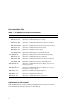
Documentation Titles Table 1 HP AlphaServer GS80 Documentation Title QA–6GAAA–G8 Order Number AlphaServer GS80/160/320 Documentation Kit EK–GS320–UG AlphaServer GS80/160/320 User’s Guide EK–GS320–RM AlphaServer GS80/160/320 Firmware Reference Manual EK–GSPAR–RM AlphaServer GS80/160/320 Getting Started with Partitions EK–GS320–IN AlphaServer GS160/320 Installation Guide EK–GSR80–IN AlphaServer GS80 Installation Guide AG–RKSW*–BE AlphaServer GS80/160/320 User Information CD QA–6GAAB–G8 AlphaSer
Chapter 1 Overview The AlphaServer GS80 systems form the low end of the family of highperformance server platforms GS80/160/320 designed for enterprise-level applications. Like the GS160/320 systems, the GS80 systems are distinguished by their versatility and high degree of expandability. This chapter gives an overview of the GS80 system with a block diagram and a physical diagram. Section 1-4 lists the system and expander cabinets with their power requirements.
1.1 The System The GS80 systems come in two Alpha microprocessor configurations: 4-processor and 8-processor. Each group of four microprocessors, along with memory and I/O modules, is designed into a single quad building block (QBB) that is housed in a drawer. Thus the systems are also designated as one-drawer and two-drawer.
System Upgrades A system upgrade is achieved in three ways: • Adding a second drawer to a single drawer system • Adding a storage device to the single-drawer system • Adding an expander cabinet to accommodate any additional I/O devices This manual details the procedures for the addition of a second drawer to the system cabinet as well as the installation of a PCI box. The addition of an expander cabinet is discussed in the AlphaServer GS80 Installation Guide (EK-GSR80-IN).
1.2 GS80 Block Diagram Figure 1–2 shows a block diagram of a two-drawer GS80 system. A distribution board makes the interconnect between the two drawers (QBBs) through their global ports.
1.3 GS80 Physical Diagram Figure 1–3 shows the physical diagram of a two-drawer GS80 system with a PCI box and an optional storage unit.
1.4 Cabinets Table 1–1 shows the model number of cabinets and power requirements for GS80 systems operating in various electrical environments. Table 1– 1 Cabinet Models and Power Requirements Cabinet Model Power Requirement System Cabinet H9A20-CA (U.S./Canada) 115-127V System Cabinet H9A20-CB (Europe) 200-240V System Cabinet H9A20-CC (U.S./Canada/Japan) Expander Cabinet H9A20-AA (U.S./Canada) Expander Cabinet H9A20-AB (Europe) Expander Cabinet H9A20-AC (U.S.
Chapter 2 System Upgrade To upgrade a one-drawer system to a two-drawer system, you must: • Install the power subrack for the second drawer • Install the second drawer System Upgrade 2-1
2.1 Installing a Power Subrack Install the power subrack first, then install the second drawer. Figure 2–1 shows how to install the power subrack.
The shipping box of the power subrack assembly contains the following items: • Subrack power supply assembly • Two base support brackets, right-hand and left-hand • Mounting kit hardware consisting of two M6 screws, six M5 screws, and four M6 nuts Refer to Figure 2–1 and install the power subrack into the cabinet as follows: 1.
2.2 Installing the Second Drawer Figure 2–2 shows a system with two drawers. To install the second drawer you must first prepare the system cabinet. Insert the drawer referring to Figures 2-2 to 2-7.
Refer to Figure 2–2 and install the second drawer as follows: 1. Install the front mounting brackets and rear brackets to the slides. Leave rear brackets slightly loose. Locate hole 28 on the left rail and hole 29 on the right rail. Ensure that the holes have U-nuts and fasten the left and right mounting brackets for the slides. 2. Mount the left side external track to the rails using two M6 screws . Do the front end first, then the rear end. Tighten mounting screws.
2.2.1 Installing the Distribution Board Assembly Remove the placeholder bracket and insert the distribution board assembly from the rear of the cabinet. Fasten it to the upper and lower drawers. See Figure 2–3.
Refer to Figure 2–3 and install the distribution board assembly as follows: 1. Pull the top drawer out of the cabinet and remove the placeholder bracket . Push the drawer back in. 2. Repeat step 1 on the lower drawer. Discard the placeholder brackets. 3. At the rear of the cabinet, push both drawers out about ten inches. Insert the distribution board assembly from the rear of the cabinet and fasten it to the upper and lower drawers .
2.2.2 Global Port, Clock, and Ground Connections Refer to Figure 2–4 to Figure 2–7 in making the global port, clock, and ground connections.
Refer to Figures 2-4 to 2-7 and make cable connections from the drawers to the distribution board assembly. Do the lower drawer first. 1. Loosen captive fasteners on the distribution board assembly and extend the lower drawer. 2. Remove drawer cover to assemble and route cables. 3. Remove the CPU and memory modules near the back left corner of the drawer. Then, remove the two screws that hold the clock compartment cover and remove the cover. Next, remove the plastic clock compartment shield. 4.
7. Carefully pull out the upper drawer while keeping the cables from the lower drawer out of the way to protect them from any damage by the distribution board assembly (see Figure 2–5). Ensure that the distribution board assembly is engaged with the lower drawer. Tighten captive fasteners. 8. Remove the CPU and memory modules near the back left corner of the drawer. Then, remove the two screws that hold the clock compartment cover and remove the cover. Next, remove the plastic clock compartment shield.
Figure 2– 5 Cable Connections-2 4 5 PK3222 to the 12. Connect the global port cables of the upper and lower drawers distribution board. Attach the plastic shield to cable B0 before plugging in its connector. Then, fold the shield up to protect the global port cables from the metal flanges. 13. Put the two covers on the distribution board assembly. Insert the tabs of the distribution board assembly covers through the chassis slots, close the with screws. (see Figure 2–7).
15. Install the ground strap to tie the drawers together . Attach one end of the ground strap to the power connector block on each drawer using one of the existing mounting screws.
Figure 2– 7 Cable Connections-4 10 9 FOLD PK3224 System Upgrade 2-13
2.2.3 Power, Signal, and CSB Connections After you have installed the second drawer, make power/signal connections between the power subrack and the drawer. Connect the drawer to the CSB (console serial bus). See Figure 2– 8.
Make the following cable connections to complete the installation of the second drawer: • Connections from the power subrack to the AC input box (if not made already) • Power signals to the drawer • 48V/48RTN; Vaux/VauxRTN connections to the drawer • Fan power/signals to the drawer • CSB connections Refer to Appendix A for a wiring diagram illustrating the above connections.
Chapter 3 PCI Box Installation This chapter gives the procedures for the installation of a PCI box. Procedures are applicable for the installation of the component in any location.
3.1 Installing a PCI Box Unpack the shipping box and note its contents. Figure 3–1 shows the PCI box.
The shipping box contains the following items: PCI box (BA54A-AA) Mounting hardware kit (CK-BA54A-AA) Table 3–1 lists the items in the PCI box mounting hardware (CK-BA54A-AA). Table 3–1 PCI Box Mounting Hardware Part Number Description CK-BA54A-AA 70-33596-01 Latch assembly 1 74-53016-01 Plate, strike 1 74-52544-01 Through cable 1 74-53597-01 Bracket, shipping 2 74-52428-01 Bracket, slide, front mounting (RH) 4 74-60022-01 Bracket, adapter, mounting 1 12-45925-01 Conn.
3.1.1 Preparing the PCI Box for Installation Figure 3–2 shows how to prepare the PCI box for installation.
Prepare the PCI box for installation as follows: 1. Slide the outer track of the mounting rail assembly of the PCI box all the way out. Press on the retaining lever to release the outer track from the assembly. 2. Repeat step 1 on the other side of the PCI box. The next step is to mount the outer tracks to the cabinet rails.
3.1.2 Preparing the Cabinet for PCI Box Installation Figure 3–3 shows how to prepare the cabinet for the PCI box installation.
Prepare the cabinet for installation as follows: 1. Select the location in the system cabinet or expander cabinet where the PCI box is to be installed. Refer to the configuration rules given in Section 3.2. to the two 2. Attach the two track mounting brackets (P/N 7452428-01) ends of the outer track bracket with two M4 x 6 truss head screws for each bracket . The front track mounting bracket has an insert for alignment.
3.1.3 Installing the PCI Box and Making Cable Connections Install the PCI box and make the cable connections. Figure 3– 4 shows how to connect the PCI box power cable and module cables.
CAUTION: Proper alignment during the insertion of the PCI box in the cabinet is critical. Two people are needed to lift the PCI box and slide it gently onto the ball bearing track. Any mishandling or misalignment at this stage could damage the hardware and result in jamming. Install the PCI box as follows: 1. Lift the PCI box and gently insert the rear sides of the inner tracks fastened on the sides of the PCI box into the outer ball bearing tracks attached to the cabinet.
3.2 Expander Cabinet Configurations The expander cabinet provides space for additional I/O components and the memory channel adapter. Figure 3– 5, Figure 3– 6, and Figure 3– 7 show various configurations for the expander cabinet. Figure 3– 7, Figure 3– 8, Figure 3– 9, and Figure 3– 10 show the locations in the expander cabinet where the I/O devices are mounted.
The expander cabinet is used for additional PCI boxes and storage devices. In addition, the expander cabinet holds two memory channel adapters for the PCI boxes. The expander cabinet is shipped with a default configuration but can be built to order as shown by other configurations. Figure 3–5, Figure 3–6, and Figure 3–7 show the various configurations available for the expander cabinet and the placement order of the I/O devices.
Figure 3– 7 Mounting Locations for the Starlight Storage Shelves Front Rails ("U" 34) Starlight - Mounting Locations Starlight 1 ("U" 33) ("U" 32) ("U" 31) Starlight 2 ("U" 30) ("U" 29) ("U" 28) Starlight 3 ("U" 27) ("U" 26) ("U" 25) Starlight 4 ("U" 24) ("U" 23) ("U" 22) Starlight 5 ("U" 21) ("U" 20) ("U" 19) Starlight 6 ("U" 18) ("U" 17) ("U" 16) Starlight 7 ("U" 15) ("U" 14) ("U" 13) Starlight 8 ("U" 12) Mount Storage Shelves so that the Front Surfaces are at or Near the Front Mounting
Figure 3– 8 Mounting Locations for the StorageWorks Storage Shelves BA356 - Hole Locations Front Rails 99 98 95 94 87 86 83 82 75 74 71 70 63 62 59 58 51 50 47 46 39 38 35 34 27 26 23 22 15 14 11 10 BA356 1 BA356 2 BA356 3 BA356 4 BA356 5 BA356 6 BA356 7 BA356 8 (Use BA35X-RK Mounting Hardw are) PK0550-00 PCI Box Installation 3-13
Figure 3– 9 Mounting Locations for the PCI Box BA54A PCI Box - Hole Locations Rear Rails Front Rails (80) PCI Box 4 (77) (80) (79) (78) (77) (75)* (74)* (72) (71) (65) PCI Box 3 (62) (65) (64) (63) (62) (60)* (59)* (57) (56) (50) PCI Box 2 (47 ) (50) (49) (48) (47) (45)* (44)* (43) (42) (35) PCI Box 1 (35) (34) (33) (32) (Location for single unit) (30)* (29)* (32 ) (27) (26) * CSB Mounting Holes. (Mounts on Rear/Right Rail Only).
Figure 3– 10 Mounting Locations for the Memory Channel Memory Channel - Hole Locations Front Rails (29) Rear Rails Memory Channel 2 (27) (26) (25) (14) (27) (26) (25) Memory Channel 1 (12) (11) (10) (12) (11) (10) Use Memory Channel 2 Rackmount Kit 2T-MAVRK PK0551-00 PCI Box Installation 3-15
Chapter 4 System Power-Up This chapter tells how to power up the system and what happens upon power-up.
4.1 Control Panel Keyswitch The operator control panel (OCP) keyswitch has three positions: Off, On, and Secure. Figure 4–1 shows the OCP keyswitch.
Table 4–1 explains the functions selected by the keyswitch. Table 4–1 Keyswitch Functions on the Control Panel Keyswitch Position Function Off System is powered off and cannot be powered on remotely. On System is powered on and can be remotely powered on or powered off. Secure System is powered on and cannot be remotely powered on or off. Refer to the AlphaServer GS80/160/320 User’s Guide or the AlphaServer GS80/160/320 Service Manual for functional descriptions of all control panel components.
4.2 Installing the System Management Console Before you power up the system, you must install the system management console (SMC). Steps to be followed in installing the SMC are listed below. The procedures to install the SMC are fully detailed in the AlphaServer GS80/160/320 System Management Console Installation Guide. Steps to Install the SMC 1. Set up the SMC PC. 2. Install the SMC terminal server in the GS80 system. 3. Connect the terminal server to the power source. 4.
4.3 Powering Up the System To power up the system, first turn the circuit breakers in all cabinets on, then set the keyswitch on the OCP to the On position. Example 4– 1 shows a sample console display on power-up. See the AlphaServer GS80/160/320 Service Manual or the AlphaServer GS80/160/320 User’s Guide for explanations of the power-up display.
Testing SIO Shared RAM(please wait) Initializing shared ram Shared RAM Initialized Powering ON H-Switch SCM_E0> ~I~ HSW4/HPM40 SysEvent: HS_INIT_CD1 Reg1:D581 Reg0:000F Phase 0 ~I~ Enable HS Links: 0f ~I~ QbbConf(gp/io/c/m)=0000bbff Assign=0f SQbb0=00 PQbb=00 SoftQbbId=0000ba98 ~I~ SysConfig: 00 00 00 00 00 00 00 00 07 1f 07 9f 37 3f 37 9f SCM_E0> ~I~ HSW4/HPM40 SysEvent: LINK0_ON Reg0:000F Reg1:D581 ~I~ HSW4/HPM40 SysEvent: LINK1_ON Reg1:D581 SCM_E0> ~I~ HSW4/HPM40 SysEvent: LINK2_ON Reg1:D581 SCM_E0> ~I
QBB0 QBB1 QBB2 QBB3 IO_MAP0: IO_MAP1: IO_MAP2: IO_MAP3: 0000A0C001333333 0000A1C101333333 0000000000000003 0000000000000003 ~I~ QbbConf(gp/io/c/m)=0000bbff Assign=0f SQbb0=00 PQbb=00 SoftQbbId=0000ba98 ~I~ SysConfig: 00 00 00 00 00 00 00 00 07 1f 07 9f 37 3f 37 9f SCM_E0> . QBB0 now Testing Step-7 QBB1 Step(s)-5 6 Tested QBB2 Step(s)-5 6 Tested QBB3 Step(s)-5 6 Tested QBB0 now Testing Step-9.. QBB0 now Testing Step-A. QBB0 now Testing Step-7 QBB0 now Testing Step-9.. QBB0 now Testing Step-A.
Phase 3 ~I~ QbbConf(gp/io/c/m)=0000bbff Assign=0f SQbb0=00 PQbb=00 SoftQbbId=0000ba98 ~I~ SysConfig: 00 00 00 00 00 00 00 00 07 1f 07 9f 37 3f 37 9f SCM_E0> . QBB0 now Testing Step-D QBB1 now Testing Step-D QBB2 now Testing Step-D QBB3 now Testing Step-D....
(-) 1/31 32.0 (-) 2/32 29.0 (-) 3/33 30.0 PPPP --PP --.- --.- P1.1 P1.0 P P P P-P PPPP P--P --.- --.- --.- --.- P P P -PP PPPP ---P --.- --.- --.- --.- P P P -PP HSwitch Type HPM40 4-port PCI Rise1-1 Cab 7 6 5 4 10 11 - - L - - - - Cables 7 6 5 4 3 2 1 0 - - - - P P P P Temp(:C) 32.0 Rise1-0 3 2 1 Rise0-1 7 6 5 4 Rise0-0 3 2 1 RIO 1 0 PS 21 Temp (:C) - - - - - - - - - - - - L - S - - S * * * * PP PP 35.0 34.5 OpenVMS PALcode V1.80-1, Tru64 UNIX PALcode V1.
lowering IPL CPU 0 speed is 731 MHz create dead_eater create poll create timer create powerup access NVRAM QBB 0 memory, 3 GB QBB 1 memory, 3 GB QBB 2 memory, 3 GB QBB 3 memory, 1 GB total memory, 10 GB copying PALcode to 10bffe0000 copying PALcode to 20bffe0000 copying PALcode to 303ffe0000 probe I/O subsystem probing hose 0, PCI probing PCI-to-ISA bridge, bus 1 bus 0, slot 1 -- pka -- QLogic ISP10x0 bus 0, slot 3 -- ewa -- DE500-BA Network Controller bus 0, slot 15 -- dqa -- Acer Labs M1543C IDE probing h
starting console on CPU 3 initialized idle PCB initializing idle process PID lowering IPL CPU 3 speed is 731 MHz create powerup starting console on CPU 4 initialized idle PCB initializing idle process PID lowering IPL CPU 4 speed is 731 MHz create powerup starting console on CPU 5 initialized idle PCB initializing idle process PID lowering IPL CPU 5 speed is 731 MHz create powerup entering idle loop starting console on CPU 6 initialized idle PCB initializing idle process PID lowering IPL CPU 6 speed is 731
lowering IPL CPU 10 speed is 731 MHz create powerup starting console on CPU 11 initialized idle PCB initializing idle process PID lowering IPL CPU 11 speed is 731 MHz create powerup starting console on CPU 12 initialized idle PCB initializing idle process PID lowering IPL CPU 12 speed is 731 MHz create powerup starting console on CPU 13 initialized idle PCB initializing idle process PID lowering IPL CPU 13 speed is 731 MHz create powerup starting console on CPU 14 initialized idle PCB initializing idle proc
The SRM console prompt (P00>>>) is displayed at the end of power-up. This completes the power-up initialization/testing sequence. The operating system can be booted and installed from the SRM console prompt. Follow instructions given in the AlphaServer GS80/160/320 User’s Guide to: • Set boot options • Boot and install Tru64 UNIX • Boot and install OpenVMS You can now run Q-VET to verify the system installation (Section 4.4).
4.4 Q-VET Installation Verification Run the latest Q-VET released version to verify the system installation. Compaq recommends running the latest Q-VET released version to verify that hardware on Tru64 UNIX and OpenVMS systems is installed correctly and is operational. Q-VET is the Qualification Verifier Exerciser Tool that is used by product engineers to exercise systems under development. Q-VET does not verify the operating system configuration.
Q-VET must be de-installed upon completion of system installation verification. Do not leave this software at a customer site; misuse may result in loss of customer data. Swap or Pagefile Space The system must have adequate swap space (on Tru64 UNIX) or PageFile space (on OpenVMS) for proper Q-VET operation. You can set this up either before or after Q-VET installation.
4.4.1 Installing Q-VET The procedures for installation of Q-VET differ between operating systems. You must install Compaq Analyze and Q-VET on each partition in the system. TCP/IP (on Tru64 UNIX) or DecNet_Phase IV (on OpenVMS) should be configured before installing Q-VET. Compaq Analyze must be installed on each partition. Q-VET will not start if Compaq Analyze is not installed. Install and run Q-VET from the SYSTEM account on VMS and the root account on UNIX.
VET. After the installation completes, you should delete the output directory with rm -r output. You can also delete the kit tar file. 8. You must reboot the system before starting Q-VET. 9. On reboot you can start Q-Vet GUI via vet& or you can run non GUI (Command Line) via vet -nw OpenVMS 1. Delete any QVETAXPxxx.A or QVETAXPxxx.EXE file from the current directory. 2. Copy the self-extracting kit image file (QVETAXPxxx.EXE) to the current directory. 3.
4.4.2 Running Q-VET You must run Q-VET on each partition in the system to verify the complete installation. Compaq recommends that you review the Testing Notes section of the Release Notes before running Q-VET. Follow the instructions listed under your operating system to run Q-VET in each partition. Choose the Long IVP script rather than the Short one. Tru64 UNIX Graphical Interface 1.
OpenVMS Graphical Interface 1. From the Main Menu, select IVP, Load Script and select Long IVP (the IVP tests will then load into the Q-VET process window). 2. Click the Start All button to begin IVP testing. Command-Line Interface $ vet /int=char Q-Vet_setup> execute ivp.vms Q-Vet_setup> start Note that commands are case sensitive. NOTE: A quick IVP script is provided for a simple verification of device setup. It is selectable from the GUI IVP menu, and the script is called .Ivp_short.scp (ivp_short.
4.4.3 Reviewing Results of the Q-VET Run After running Q-VET, check the results of the run by reviewing the Summary Log. If you run Q-VET as instructed, Q-VET will terminate testing after the slowest test has completed one pass and produce a Summary file. The termination message will tell you the name and location of this file. All exerciser processes are terminated automatically when the RunTime expires or manually via the Terminate command.
4.
4.4.4 De-Installing Q-VET The procedures for de-installation of Q-VET differ between operating systems. You must de-install Q-VET from each partition in the system. You must de-install Q-VET from each partition. Failure to do so may result in the loss of customer data at a later date if Q-VET is misused. Follow the instructions listed under your operating system to de-install Q-VET from a partition.
Appendix A GS80 Interconnection Diagram Figure A–1 shows the interconnection diagram of the GS80 system. Use this diagram as a guide for cabling when doing system upgrades.
Figure A–1 GS80 Interconnection Diagram Terminator 12-45926-01 (At End of CSB Bus) 17-04736-01 2nd Storage (Optional) BA54A PCI - No. 2 or BA356 - No. 1 or Storage - No. 1 (Optional) BA54A PCI No. 1 OCP Assembly J-2 J-1 BA52A (4P) No. 1 BA52A (4P) No.
Appendix B Upgrades Using B4166 and B4168 CPUs Upgrading original systems depends upon whether the customer decides to retain the older, slightly slower CPUs or not. There are three types of upgrades: • Adding CPUs to a (black) system that always had B4166 CPUs. • Replacing B4125 CPUs in a (blue) system with B4166 or B4168 CPUs. • Adding B4166 or B4168 CPUs to a (blue) system containing B4125 CPUs.
B.1 Upgrades Retaining Older CPUs These upgrades consist of adding new CPUs, and possibly, a new system drawer. See Chapter 2 for procedures on how to add a new system drawer. Figure B–1 shows how to install a CPU. Table B-1 describes the different CPUs. The CPU derives its operating clock speed from the system clock. The B4125 CPU is not supported when the system clock is run at 9.0 ns. NOTE: Be sure to update the firmware. See Section B.2.
1. Check the firmware revisions and update, if necessary. 2. Ensure that the color code of the CPU module matches the color code of the slot. 3. Push the retainers on the module latches with your thumbs in the direction of the arrows and release the latch. 4. Slide the module into the slot guide and gently push it in until the latches are activated. 5. Close the latches onto the bulkhead and push them in until you hear one or two clicks. The module is now firmly seated in the slot.
Table B– 1 Comparison of CPUs (Continued) CPU Part Number B-cache Size Speed in MHz B4168 Uses 4 of its 16 MB B-cache 1148 The B4168 runs at this speed when placed in a QBB that supports only 4 Mbytes of B-cache, when all CPUs in the system are B4168 or B4166, and the clock runs at 9.0 ns. Uses 8 of its 16 MB B-cache 1001 The B4168 runs at this speed and uses 8 Mbytes of its B-cache when the B4168 is placed in the same QBB as the B4166 and the clock is at 9.0 ns.
From outside the drawer, there is no easy way to visually distinguish between the two system drawers; to see the components that differ requires looking inside the drawer. The best way to determine which drawer is in the system is to use the show fru command. The 54-class part number is listed on the QBBx line when the show fru command is issued from either the SCM monitor or the SRM console. Configuration Rules The original (blue) system upgrade is governed by the following rules: 1.
B.2 Upgrades Replacing Older CPUs First, update the system firmware and then replace the old CPU(s). See Figure B– 1. Finally, change the speed of the system clock. Example B– 1 Updating the Firmware P00>>> show config Compaq Computer Corporation Compaq AlphaServer GS80 6/731 SRM Console PALcode V5.8-1, built on May 26 2000 at 12:15:01 OpenVMS PALcode V1.81-1, Tru64 UNIX PALcode V1.75-1 Micro Firmware V5.
Issue the SRM show config command. Note the version of the SRM console. The B4166 requires V6.0-514 or higher, and the B4168 requires V6.3 or higher. Note the firmware revision of the microprocessors. The B4166 requires V6.0-514 or higher, and the B4168 requires V6.3 or higher. Issue the SCM command to get to the SCM monitor. Only necessary if the system is partitioned. Issue the set hp_count 0 command if the system is partitioned.
B.3 Changing the Clock Module Switch Settings Two switch packs on the clock module control the clock frequency. If no B4125 CPUs are in the system, the clock can run at the faster speed (9.0 ns). Figure B– 2 System Clock Switch Packs 52.2 MHz/9.6 ns S1 S2 1 2 3 4 S2 1 S1 0 1 2 3 4 5 6 0 1 55.6 MHz/9.
The switch packs on the master clock control the speed of the system. When B4125 CPUs are in the system, the clock runs at 9.6 ns. To set the system speed to 9.0 ns, access the clock module and change the switches.
1. Access the top system drawer and remove CPU3 and memory 2 to allow space to access the clock module. 2. Remove the clock module cover plate in the rear left corner of the drawer compartment by removing the two Phillips head screws holding it in place and lift it out of the drawer. 3. Remove the clock compartment shield. Note how the shield is installed. 4. Unplug the coax clock cable(s) from the clock module. 5. Unplug the power cable. 6.
B.4 B4168 Compatibility Switch The B4168 CPU module has a switch that must be set if the module is to be used with B4125 modules in the same QBB. Figure B– 4 Setting the B4168 Switch For use with B4168 or B4166 CPUs For use with B4125 CPUs S1 Switch Power Converter CPU Chip MR0489 Figure B–4 shows the location of the S1 switch that must be changed if the module is to be in a QBB with a B4125 module.
B.5 Verification When you power up the system, check that the SCM correctly maps the QBBs in the system. Execute the SRM set sys_serial_num command. Run Q-Vet (see Section 4.4.2).
B.6 Replacing the System Cosmetics After a system is completely upgraded, new cabinet doors, sides, and top may be installed.
Door Removal 1. 2. If the door has a service pouch on it, remove it and place it inside the cabinet. 3. Disconnect all cables to the OCP. 4. Remove the outer screw of the upper bracket holding the door to the frame. 5. Loosen the inner screw of the upper bracket and slide the door and bracket to let the screw pass through the bracket. 6. Tilt the door away from the cabinet and lift it off the bottom bracket. Open the front door and remove the screw at the cabinet end of the ground strap.
Index B Block diagram, 1-3 C Cabinet preparation, 3-6 Cabinets, 1-5 Clock connections, 2-8 Configurations, expander cabinet, 3-10 Connections clock, 2-8 CSB, 2-14 global port, 2-8 ground, 2-8 PCI box, 3-8 power, 2-14 signal, 2-14 Control panel keyswitch, 4-1, 4-2 CPU switch, 1-11 CPU upgrades, 1-3 CSB connections, 2-14 D De-installing Q-VET, 4-22 Distribution board assembly, 2-6 E Expander cabinet configurations, 3-10 G Global port connections, 2-8 Ground connections, 2-8 GS80 block diagram, 1-3 GS80 p
Q QBB, 1-2 Q-VET installation verification, 4-14 Q-VET results review, 4-20 R Running Q-VET, 4-18 S Second drawer installation, 2-4 Index-2 Signal connections, 2-14 SMC, 4-4 System management console, 4-4 System upgrades, 1-3 U Upgrades CPU, 1-3, B-1 system, 1-3