
HP Z210 CMT Workstation Maintenance and Service Guide
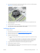
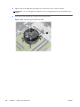
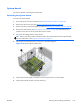
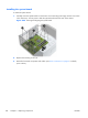

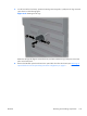
Table Of Contents
- Product overview
- Setting up the operating system
- Restoring the operating system
- System management
- BIOS ROM
- The Computer Setup (F10) Utility
- Desktop management
- Initial computer configuration and deployment
- Installing a remote system
- Replicating the setup
- Updating and managing software
- HP Client Manager Software
- Altiris Client Management Solutions
- HP SoftPaq Download Manager
- System Software Manager
- ROM Flash
- FailSafe Boot Block ROM
- Workstation security
- Asset tracking
- SATA hard disk drive security
- Password security
- Establishing a setup password using Computer Setup (F10) Utility
- Establishing a power-on password using computer setup
- Entering a power-on password
- Entering a setup password
- Changing a power-on or setup password
- Deleting a power-on or setup password
- National keyboard delimiter characters
- Clearing passwords
- Chassis security
- Fault notification and recovery
- Dual-state power button
- Replacing components
- Warnings and cautions
- Service considerations
- Customer Self-Repair
- Removing and installing components
- Component locations
- Predisassembly procedures
- Disassembly order
- Removing the cable lock (optional)
- Side access panel
- Side access panel sensor (optional)
- Side access panel solenoid lock
- Bezel
- Front panel I/O device assembly
- Optical disk drive (mini-tower configuration)
- Optical disk drive (desktop configuration)
- Speaker
- Power supply
- Power connections
- Rear system fan assembly
- Memory
- Expansion card slot identification
- Expansion card
- Battery
- Hard disk drive
- CPU heatsink
- CPU
- System board
- Converting to desktop configuration
- Product recycling
- Diagnostics and troubleshooting
- Calling technical support
- Locating ID labels
- Locating warranty information
- Diagnosis guidelines
- Troubleshooting checklist
- HP troubleshooting resources and tools
- Troubleshooting scenarios and solutions
- Self-troubleshooting with HP Vision Diagnostics
- Diagnostic codes and errors
- Configuring RAID devices
- Configuring password security and resetting CMOS
- Connector pins
- System board designators
- Routine Care
- Locating HP resources
- Index
System board
This section describes replacing the system board.
Removing the system board
To remove the system board:
1. Disconnect power from the workstation (see
Predisassembly procedures on page 62).
2. Remove the side access panel (see
Removing the side access panel on page 65).
3. Remove expansion boards and graphics cards (see
Removing an expansion card on page 90).
4. Remove the CPU heatsink (see
Removing the CPU heatsink on page 98). Note that the CPU
heatsink screws also secure the system board to the chassis.
5. Disconnect all cabling from the system board.
TIP: Make a note of the cable connections before disconnecting them from the system board.
For more information, refer to
Power connections on page 81.
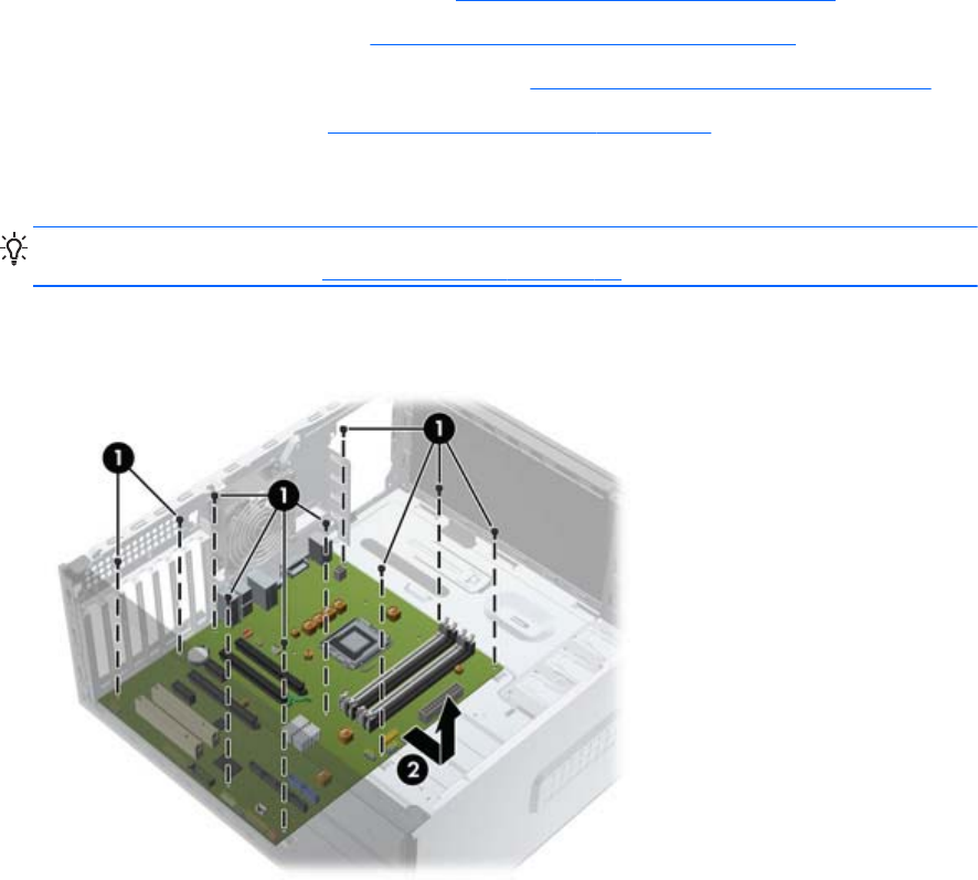
6. Remove the ten mounting screws (1) as shown in the following figure.
Figure 5-43 Removing the system board
7. Lift the system board slightly, and pull the board away from the rear of the chassis.
8. Lift the system board upward out of the chassis (2).
ENWW
Removing and installing components
103