
HP Z210 CMT Workstation Maintenance and Service Guide


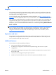

Table Of Contents
- Product overview
- Setting up the operating system
- Restoring the operating system
- System management
- BIOS ROM
- The Computer Setup (F10) Utility
- Desktop management
- Initial computer configuration and deployment
- Installing a remote system
- Replicating the setup
- Updating and managing software
- HP Client Manager Software
- Altiris Client Management Solutions
- HP SoftPaq Download Manager
- System Software Manager
- ROM Flash
- FailSafe Boot Block ROM
- Workstation security
- Asset tracking
- SATA hard disk drive security
- Password security
- Establishing a setup password using Computer Setup (F10) Utility
- Establishing a power-on password using computer setup
- Entering a power-on password
- Entering a setup password
- Changing a power-on or setup password
- Deleting a power-on or setup password
- National keyboard delimiter characters
- Clearing passwords
- Chassis security
- Fault notification and recovery
- Dual-state power button
- Replacing components
- Warnings and cautions
- Service considerations
- Customer Self-Repair
- Removing and installing components
- Component locations
- Predisassembly procedures
- Disassembly order
- Removing the cable lock (optional)
- Side access panel
- Side access panel sensor (optional)
- Side access panel solenoid lock
- Bezel
- Front panel I/O device assembly
- Optical disk drive (mini-tower configuration)
- Optical disk drive (desktop configuration)
- Speaker
- Power supply
- Power connections
- Rear system fan assembly
- Memory
- Expansion card slot identification
- Expansion card
- Battery
- Hard disk drive
- CPU heatsink
- CPU
- System board
- Converting to desktop configuration
- Product recycling
- Diagnostics and troubleshooting
- Calling technical support
- Locating ID labels
- Locating warranty information
- Diagnosis guidelines
- Troubleshooting checklist
- HP troubleshooting resources and tools
- Troubleshooting scenarios and solutions
- Self-troubleshooting with HP Vision Diagnostics
- Diagnostic codes and errors
- Configuring RAID devices
- Configuring password security and resetting CMOS
- Connector pins
- System board designators
- Routine Care
- Locating HP resources
- Index
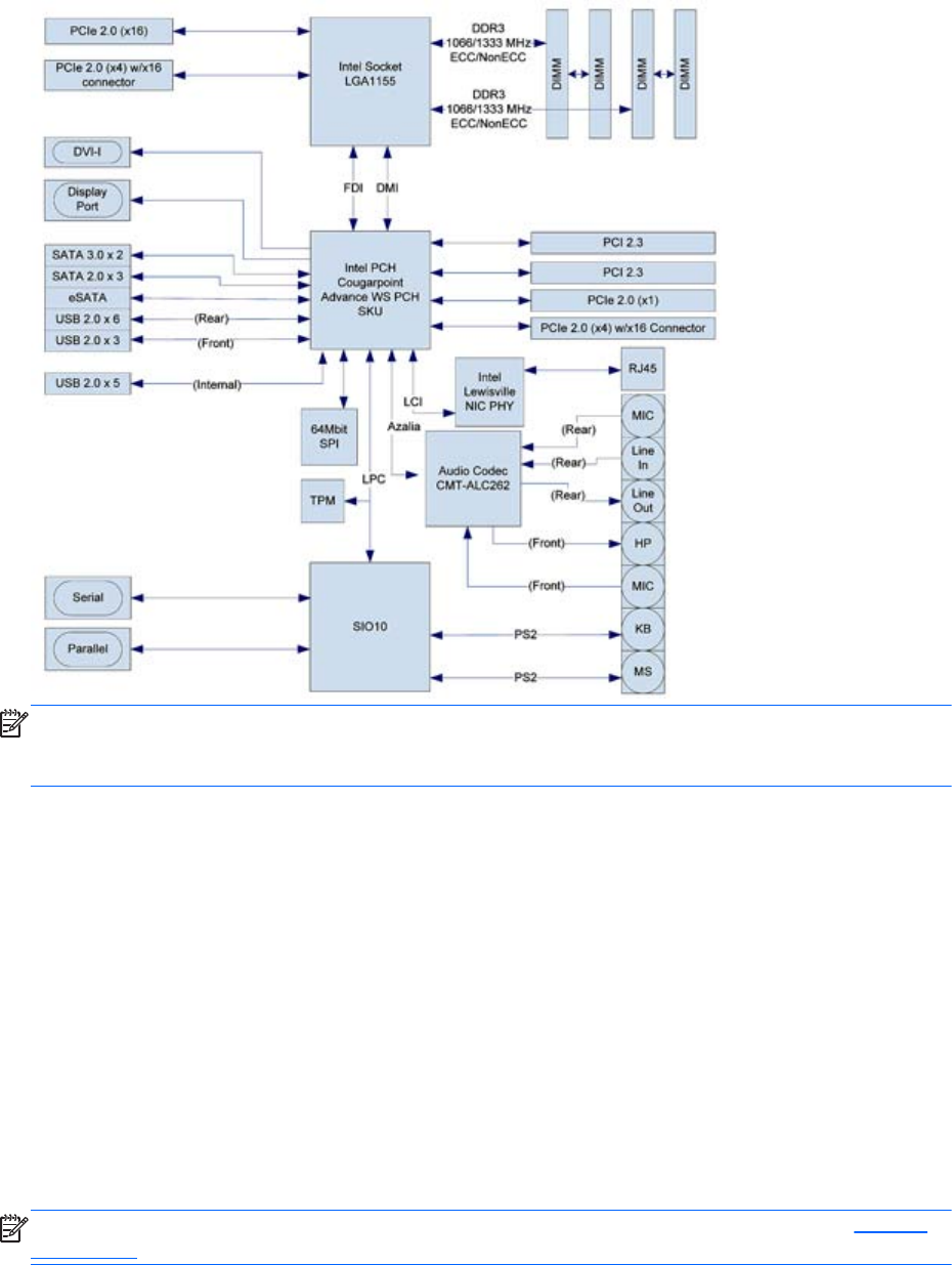
The following figure shows the typical system board block diagram.
Figure 1-1 System board block diagram
NOTE: The x1, x4, and x16 designators describe the mechanical length of the slot. The number in
parentheses lists the number of electrical PCIe lanes routed to the expansion slot. For example, x16(4)
means that the expansion slot is mechanically a x16 length connector, with four PCIe lanes connected.
Processor technology
This workstation uses the latest 32nm process SKT-H2 chipset, with support for the Intel® Xeon®
Processor E3 Family or 2nd generation Intel Core(TM) processors up to 95W. These processors
incorporate an integrated 2-channel memory controller, microarchitecture improvements, integrated
graphics (some models) and Advanced Vector Extensions (AVX) to increase floating point performance.
In addition, the chipset uses the Intel DMIx4 interface to connect the processor and I/O controller.
Memory technology
The workstation dual in-line memory modules (DIMMs) are based on DDR3 1066/1333MHz
technology. Error checking and correcting (ECC) and non-ECC DIMMs are supported. Two direct-attach
memory channels permit low latency access and fast data transfer to improve performance. System
memory sizes up to 32GB (using 8GB DIMMs) are supported.
NOTE: To optimize performance, distribute the DIMMs across both memory channels. See Memory
on page 83 for more information.
2 Chapter 1 Product overview ENWW