
HP Z210 CMT Workstation Maintenance and Service Guide

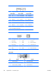
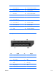
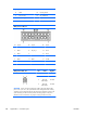
Table Of Contents
- Product overview
- Setting up the operating system
- Restoring the operating system
- System management
- BIOS ROM
- The Computer Setup (F10) Utility
- Desktop management
- Initial computer configuration and deployment
- Installing a remote system
- Replicating the setup
- Updating and managing software
- HP Client Manager Software
- Altiris Client Management Solutions
- HP SoftPaq Download Manager
- System Software Manager
- ROM Flash
- FailSafe Boot Block ROM
- Workstation security
- Asset tracking
- SATA hard disk drive security
- Password security
- Establishing a setup password using Computer Setup (F10) Utility
- Establishing a power-on password using computer setup
- Entering a power-on password
- Entering a setup password
- Changing a power-on or setup password
- Deleting a power-on or setup password
- National keyboard delimiter characters
- Clearing passwords
- Chassis security
- Fault notification and recovery
- Dual-state power button
- Replacing components
- Warnings and cautions
- Service considerations
- Customer Self-Repair
- Removing and installing components
- Component locations
- Predisassembly procedures
- Disassembly order
- Removing the cable lock (optional)
- Side access panel
- Side access panel sensor (optional)
- Side access panel solenoid lock
- Bezel
- Front panel I/O device assembly
- Optical disk drive (mini-tower configuration)
- Optical disk drive (desktop configuration)
- Speaker
- Power supply
- Power connections
- Rear system fan assembly
- Memory
- Expansion card slot identification
- Expansion card
- Battery
- Hard disk drive
- CPU heatsink
- CPU
- System board
- Converting to desktop configuration
- Product recycling
- Diagnostics and troubleshooting
- Calling technical support
- Locating ID labels
- Locating warranty information
- Diagnosis guidelines
- Troubleshooting checklist
- HP troubleshooting resources and tools
- Troubleshooting scenarios and solutions
- Self-troubleshooting with HP Vision Diagnostics
- Diagnostic codes and errors
- Configuring RAID devices
- Configuring password security and resetting CMOS
- Connector pins
- System board designators
- Routine Care
- Locating HP resources
- Index
Display port
8 GND 18 Hot Plug Detect
9 ML_Lane 2(n) 19 DP_PWR Return
10 ML_Lane 3(p) 20 DP_PWR
Main power cable, P1
Pin Signal Pin Signal Pin Signal
15V 7- 13V12–B
2GND 8PS_ON_L 14V12–S
3GND 9- 15V12–S
4 GND 10 5V 16 -
5 GND 11 GND 17 11VSB
6 GND 12 V12–B 18 V12N
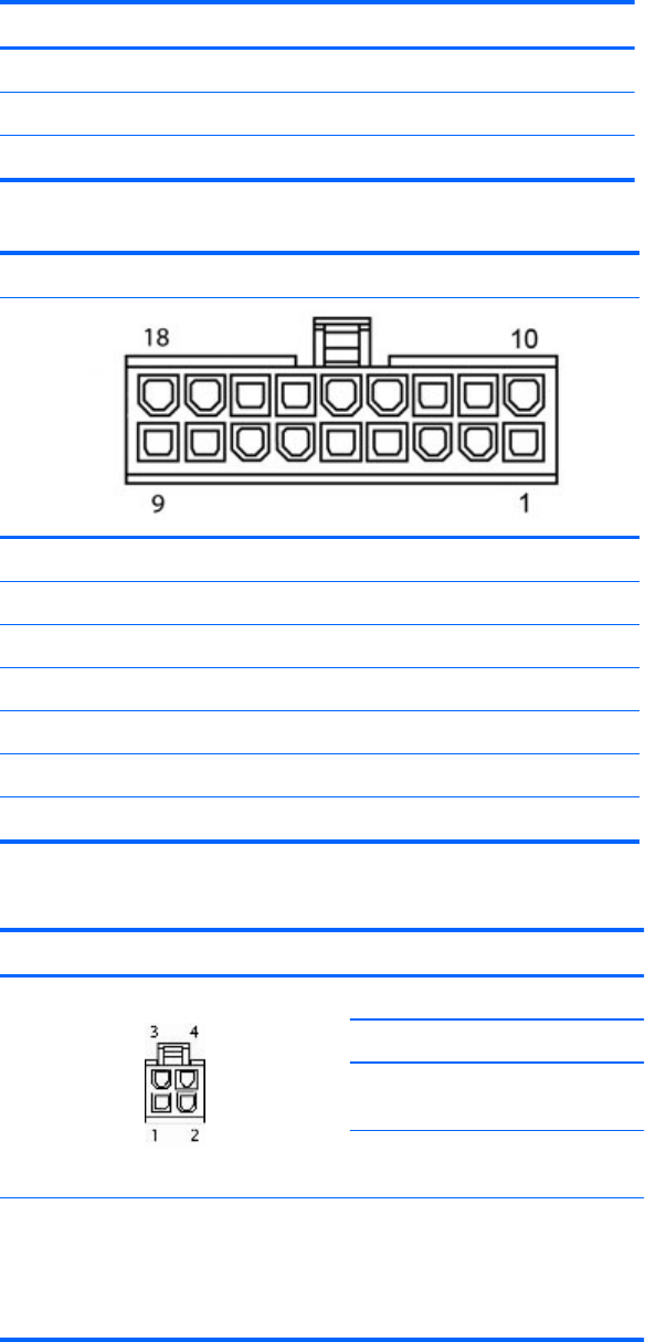
CPU power cable, P3 Pin Color Signal
1BLK GND
2BLK GND
3BLK with
BRN stripes
V12CPU
4BLK with
BRN stripes
V12CPU
CAUTION: Never connect the CPU power cable to the system board while
power is on. If you do so, the system board can be damaged and the warranty
voided. Be sure to distinguish between the CPU power cable that connects to the
system board (4-pin white connector) and the Auxiliary graphics card power
cable that connects to the PCIe x16 graphics card (6-pin black connector).
158 Appendix A Connector pins ENWW