
HP Z210 CMT Workstation Maintenance and Service Guide
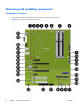
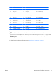


Table Of Contents
- Product overview
- Setting up the operating system
- Restoring the operating system
- System management
- BIOS ROM
- The Computer Setup (F10) Utility
- Desktop management
- Initial computer configuration and deployment
- Installing a remote system
- Replicating the setup
- Updating and managing software
- HP Client Manager Software
- Altiris Client Management Solutions
- HP SoftPaq Download Manager
- System Software Manager
- ROM Flash
- FailSafe Boot Block ROM
- Workstation security
- Asset tracking
- SATA hard disk drive security
- Password security
- Establishing a setup password using Computer Setup (F10) Utility
- Establishing a power-on password using computer setup
- Entering a power-on password
- Entering a setup password
- Changing a power-on or setup password
- Deleting a power-on or setup password
- National keyboard delimiter characters
- Clearing passwords
- Chassis security
- Fault notification and recovery
- Dual-state power button
- Replacing components
- Warnings and cautions
- Service considerations
- Customer Self-Repair
- Removing and installing components
- Component locations
- Predisassembly procedures
- Disassembly order
- Removing the cable lock (optional)
- Side access panel
- Side access panel sensor (optional)
- Side access panel solenoid lock
- Bezel
- Front panel I/O device assembly
- Optical disk drive (mini-tower configuration)
- Optical disk drive (desktop configuration)
- Speaker
- Power supply
- Power connections
- Rear system fan assembly
- Memory
- Expansion card slot identification
- Expansion card
- Battery
- Hard disk drive
- CPU heatsink
- CPU
- System board
- Converting to desktop configuration
- Product recycling
- Diagnostics and troubleshooting
- Calling technical support
- Locating ID labels
- Locating warranty information
- Diagnosis guidelines
- Troubleshooting checklist
- HP troubleshooting resources and tools
- Troubleshooting scenarios and solutions
- Self-troubleshooting with HP Vision Diagnostics
- Diagnostic codes and errors
- Configuring RAID devices
- Configuring password security and resetting CMOS
- Connector pins
- System board designators
- Routine Care
- Locating HP resources
- Index

Table 5-2 System board components ID
Item Component Item Component Item Component
1 Rear chassis fan 13 Battery 25 PCIe2 x1
2 CPU power 14
SATA ports
1
26 PCIe2 x16(4)
3 Solenoid hood lock 15 Clear CMOS button 27 PCIe2 x1
4 Chassis intrusion 16 Crisis recovery jumper 28 PCIe2 x16
5 CPU socket 17 Front chassis fan 29 PCIe2 x8(4)
6 CPU fan 18 System speaker 30 Audio
7 Memory sockets 19 3rd internal USB 31 USB
8 Main Power 20 Password jumper 32 Network/USB
9 Front power button/LED 21 Serial 33
DP display port
2
10 Front USB 22 Parallel 34
DVI —I video
2
11 1st internal USB/DASH 23 Front audio 35 Keyboard/mouse
12 2nd internal USB 24 PCI 32/33
1
Blue SATA ports, namely SATA0 and SATA1, support SATA Gen3 (6 Gb). Note that SATA5 is the only eSATA compatible
port.
2
Intel integrated HD video is supported on some workstation models, depending on installed CPU. Most supported Intel Core
processors support Intel HD Graphics 2000. Intel Xeon processors with model designations that end in "---5" support Intel HD
Graphics P3000. In Windows 7, you can view the model of CPU installed in the workstation by selecting Start > Control
Panel > System .
For related system architecture information, see System board architecture on page 1.
ENWW
Removing and installing components
61