HP EliteBook 8460w Mobile Workstation HP EliteBook 8460p Notebook PC HP ProBook 6460b Notebook PC Maintenance and Service Guide
© Copyright 2011, 2012 Hewlett-Packard Development Company, L.P. Bluetooth is a trademark owned by its proprietor and used by Hewlett-Packard Company under license. Intel and Core are trademarks or registered trademarks of Intel Corporation in the United States and other countries. Microsoft, Windows, and Windows Vista are either trademarks or registered trademarks of Microsoft Corporation in the United States and/or other countries. SD Logo is a trademark of its proprietor.
Safety warning notice WARNING! To reduce the possibility of heat-related injuries or of overheating the computer, do not place the computer directly on your lap or obstruct the computer air vents. Use the computer only on a hard, flat surface. Do not allow another hard surface, such as an adjoining optional printer, or a soft surface, such as pillows or rugs or clothing, to block airflow.
iv Safety warning notice
Table of contents 1 Product description ........................................................................................................................................ 1 2 External component identification .............................................................................................................. 10 Display ................................................................................................................................................ 10 Top ......................
Drive handling ................................................................................................... 57 Grounding guidelines ......................................................................................................... 58 Electrostatic discharge damage ........................................................................ 58 Packaging and transporting guidelines ............................................. 59 Workstation guidelines ...............................................
Restoring factory settings in Computer Setup ................................................................. 124 Updating the BIOS ........................................................................................................... 125 Determining the BIOS version ......................................................................... 125 Downloading a BIOS update ........................................................................... 125 Using System Diagnostics .............................
viii
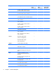
1 Product description Category Description Product Name HP ProBook 6460p Notebook PC HP ProBook 6460b Notebook PC HP EliteBook 8460p Notebook PC √ HP EliteBook 8460p Notebook PC √ HP EliteBook 8460w Mobile Workstation Processors HP EliteBook 8460w Mobile Workstation √ Intel® Core™ i7 processor, Quad Core 2860M, 2.50-GHz (Turbo up to 3.60) processor 8-MB L3 cache, 8 threads √ √ 2820M, 2.30-GHz (Turbo up to 3.40) processor 8-MB L3 cache, 8 threads √ √ 2760M, 2.40-GHz (Turbo up to 3.
Category Description HP ProBook 6460b Notebook PC HP EliteBook 8460p Notebook PC 2430M, 2.40-GHz (Turbo up to 3.00) processor 3-MB L3 cache, 4 threads √ √ 2410M, 2.30-GHz (Turbo up to 2.90) processor 3-MB L3 cache, 4 threads √ √ HP EliteBook 8460w Mobile Workstation Intel Core i3 processors, Dual Core (not available with iAMT, Intel QM67 chipset) 2370M, 2.40-GHz processor 3-MB L3 cache, 4 threads √ 2350M, 2.30-GHz processor 3-MB L3 cache, 4 threads √ 2330M, 2.
Category Memory Description HP ProBook 6460b Notebook PC HP EliteBook 8460p Notebook PC HP EliteBook 8460w Mobile Workstation 35.6-cm (14.0-in) HD, anti-glare, LED SVA (1366x768) with camera √ √ √ 35.6-cm (14.0-in) HD+, anti-glare, LED SVA (1600x900) with camera √ √ √ 35.6-cm (14.0-in) HD, anti-glare, LED SVA (1366x768) with camera and WWAN √ √ √ 35.6-cm (14.
Category Description Supports the following drives: HP ProBook 6460b Notebook PC HP EliteBook 8460p Notebook PC HP EliteBook 8460w Mobile Workstation √ √ √ √ √ √ Fixed √ √ √ Customer-accessible √ √ √ Serial ATA √ √ √ 12.7-mm tray load √ √ √ Supports “No Drive” option √ √ √ Supports the following 12.
Category Ethernet Wireless Description HP ProBook 6460b Notebook PC HP EliteBook 8460p Notebook PC HP EliteBook 8460w Mobile Workstation Supports “No Modem” option √ √ √ Intel 82579LM GbE LAN 10/100/1000 network interface card (NIC) with iAMT (vPro models) √ √ √ Intel 82579V GbE LAN 10/100/1000 network interface card (non-vPro models) √ S3/S4/S5 wake on LAN √ √ √ NIC power down technology √ √ √ Ethernet cable not included √ √ √ √ √ Integrated WLAN options by way of wireless mo
Category Description Supports the following WWAN modules: ● Qualcomm Gobi 3000 HSPA/ CDMA with GPS ● Ericsson 5521 HSPA+ ● HP lt2510 EV-DO/LTE Mobile Broadband Module HP ProBook 6460b Notebook PC √ HP EliteBook 8460p Notebook PC HP EliteBook 8460w Mobile Workstation √ √ Integrated personal area network (PAN) options by way of Bluetooth® module: External media card Ports Supports “no PAN” option √ √ √ Integrated Bluetooth 2.
Category Power requirements Security Operating system Description HP ProBook 6460b Notebook PC HP EliteBook 8460p Notebook PC HP EliteBook 8460w Mobile Workstation Touchpad includes: on/off button, supports 2-way scroll with legend, taps enabled by default, 2-finger scrolling and zoom enabled by default √ √ √ Smart AC adapter with localized cable plug support (3-wire plug with ground pin, supports 3-pin DC connector): √ √ √ 9-cell, 3.0-Ah (100-Wh) Li-ion battery √ √ √ 6-cell, 2.
Category Description FreeDOS HP ProBook 6460b Notebook PC HP EliteBook 8460p Notebook PC HP EliteBook 8460w Mobile Workstation √ √ √ Windows 7 Professional 32 with Microsoft Office 2010 Starter √ √ √ Windows 7 Professional 32 with Microsoft Office 2010 Personal √ √ √ Windows 7 Professional 32 with Microsoft Office 2010 Home & Business √ √ √ Windows 7 Professional 32 with Microsoft Office 2010 Professional √ √ √ Windows 7 Professional 64 with Microsoft Office 2010 Starter √ √ √ W
Category Description Windows Vista Basic 32 with Microsoft Office 2010 Professional HP ProBook 6460b Notebook PC HP EliteBook 8460p Notebook PC HP EliteBook 8460w Mobile Workstation √ √ √ Windows 7 Professional 64 √ √ √ Windows 7 Professional 32 √ √ √ Windows 7 Home Basic 32 √ √ √ Windows 7 Home Premium 64 √ √ √ Windows 7 Home Premium 32 √ √ √ Windows 7 Starter 32 √ DRDVD Windows 7 √ √ √ DRDVD Windows 7 with WinDVD √ √ √ √ √ Restore Media: Web-only support: Windows
2 External component identification Display NOTE: Refer to the illustration that most closely matches your computer. Component Description (1) Turns off the display or initiates Sleep if the display is closed while the power is on. Internal display switch NOTE: The display switch is not visible from the outside of the computer. 10 (2) WLAN antennas (3)* Send and receive wireless signals to communicate with wireless local area networks (WLAN).
Component Description (5) Webcam light (select models only) On: The webcam is in use. (6) Webcam (select models only) Records video and captures still photographs. To use the webcam, select Start > All Programs > HP > HP Webcam. (7) Ambient light sensor When activated, the sensor automatically adjusts the display brightness based on the lighting conditions in your environment. (8) Keyboard light On: When the keyboard light is activated.
Component Description (6) Records video and captures still photographs. Webcam (select models only) To use the webcam, select Start > All Programs > HP > HP Webcam. *The antennas are not visible from the outside of the computer. For optimal transmission, keep the areas immediately around the antennas free from obstructions. To see wireless regulatory notices, refer to the section of the Regulatory, Safety and Environmental Notices that applies to your country or region.
Top TouchPad NOTE: Your computer may look slightly different from the illustration in this section. Component Description (1) Pointing stick (select models only) Moves the pointer and selects or activates items on the screen. (2) Left pointing stick button Can be used with the pointing stick and functions like the left button on an external mouse. (3) TouchPad on/off button Turns the TouchPad on and off. (4) TouchPad Moves the pointer and selects or activates items on the screen.
Lights NOTE: Refer to the illustration that most closely matches your computer. Component (1) 14 Description TouchPad on/off light ● Amber: The TouchPad is off. ● Off: The TouchPad is on. (2) Caps lock light On: Caps lock is on. (3) Power light ● On: The computer is on. ● Blinking: The computer is in the Sleep state. ● Off: The computer is off or in Hibernation.
Component (4) (5) Description Wireless light QuickWeb light ● White: An integrated wireless device, such as a wireless local area network (WLAN) device and/or a Bluetooth® device, is on. ● Amber: All wireless devices are off. ● On: The computer is on. ● Off: The computer is off or in Hibernation. NOTE: For more information, refer to “HP QuickWeb” in this guide and to the HP Quickweb software Help (6) (7) Mute light Num lock light ● Amber: Computer sound is off.
Buttons and fingerprint reader NOTE: Refer to the illustration that most closely matches your computer. Component (1) 16 Description TouchPad on/off button Chapter 2 External component identification Turns the TouchPad on and off.
Component (2) Description Power button ● When the computer is off, press the button to turn on the computer. ● When the computer is on, press the button briefly to initiate Sleep. ● When the computer is in the Sleep state, press the button briefly to exit Sleep. ● When the computer is in Hibernation, press the button briefly to exit Hibernation.
Keys NOTE: Refer to the illustration that most closely matches your computer. Component 18 Description (1) esc key Displays system information when pressed in combination with the fn key. (2) Function keys Execute frequently used system functions when pressed in combination with the fn key.
Component Description (3) fn key Executes frequently used system functions when pressed in combination with a function key, the num lk key, or the esc key. (4) Start key Displays the Start menu. (5) Menu key Displays the active program’s shortcut menu (same as right-click menu). (6) Embedded numeric keypad keys Can be used like the keys on an external numeric keypad when pressed in combination with the fn and num lk keys.
Front NOTE: Component Description (1) Display release latch Opens the computer. (2) Wireless light ● White: An integrated wireless device, such as a wireless local area network (WLAN) device and/or a Bluetooth® device, is on. ● Amber: All wireless devices are off. ● On: The computer is on. ● Blinking: The computer is in the Sleep state. ● Off: The computer is off or in Hibernation. ● Amber: The computer is connected to external power and the battery is charged from 0 – 90%.
Component Description (5) ● Blinking turquoise: The hard drive or optical drive is being accessed. ● Amber: HP 3D DriveGuard has temporarily parked the hard drive. Hard drive light (6) Speaker Produces SRS Premium sound (select models only). NOTE: To use the SRS Premium sound software, select Start > All Programs > SRS Premium Sound. Left NOTE: Refer to the illustration that most closely matches your computer. Component Description (1) Power connector Connects an AC adapter.
Rear NOTE: Refer to the illustration that most closely matches your computer. Component 22 Description (1) RJ-11 (modem) jack Connects a modem cable. (2) External monitor port Connects an external VGA monitor or projector. (3) RJ-45 (network) jack Connects a network cable.
Right NOTE: Refer to the illustration that most closely matches your computer. Component (1) Description Audio-out (headphone) jack Produces sound when connected to optional powered stereo speakers, headphones, ear buds, a headset, or television audio. NOTE: When a device is connected to the headphone jack, the computer speakers are disabled. (2) Audio-in (microphone) jack Connects an optional computer headset microphone, stereo array microphone, or monaural microphone.
Component (1) Description Audio-out (headphone) jack Produces sound when connected to optional powered stereo speakers, headphones, ear buds, a headset, or television audio. NOTE: When a device is connected to the headphone jack, the computer speakers are disabled. (2) Audio-in (microphone) jack Connects an optional computer headset microphone, stereo array microphone, or monaural microphone.
Bottom Component (1) Description Vents (3) Enable airflow to cool internal components. NOTE: The computer fan starts up automatically to cool internal components and prevent overheating. It is normal for the internal fan to cycle on and off during routine operation. (2) Battery release latch Releases the battery from the battery bay. (3) Docking connector Connects an optional docking device. (4) Bottom cover release latch Releases or locks the bottom cover.
Component Description (9) Bluetooth compartment Contains a Bluetooth device. (10) Wireless and memory module compartments and hard drive bay Hold an HP Mobile Broadband Module, the memory modules, and the hard drive. NOTE: To prevent an unresponsive system, replace the wireless module only with a wireless module authorized for use in the computer by the governmental agency that regulates wireless devices in your country or region.
3 Illustrated parts catalog Service tag When ordering parts or requesting information, provide the computer serial number and model description provided on the service tag. ● Product name (1). This is the product name affixed to the front of the computer. ● Serial number (s/n) (2). This is an alphanumeric identifier that is unique to each product. ● Part number/Product number (p/n) (3). This number provides specific information about the product's hardware components.
Computer major components 28 Chapter 3 Illustrated parts catalog
Item Description Spare part number (1) Display panel not spared NOTE: (2) Keyboard (includes cable) NOTE: (3) For a list of display panel spare parts, see Display components on page 36. For a detailed list of available keyboards, see Sequential part number listing on page 43.
Item Description Spare part number ● For use in computers with WLAN, with WWAN, no vPro (4M) 642751-001 ● For use in computers with vPro (8M), WLAN, with WWAN, and 512-MB graphics 642753-001 ● For use in computers with vPro (8M), WLAN, with WWAN, and 1-GB graphics 642754-001 ● For use in computers with vPro (8M), WLAN, with WWAN, 1-GB graphics, and USB 3.
Item Description Spare part number Broadcom 43224AGN 802.
Item 32 Description Spare part number Intel Wi-Fi Link 1000 for use in Andorra, Antigua and Barbuda, Argentina, Aruba, Australia, Austria, Azerbaijan, Bahamas, Bahrain, Barbados, Belgium, Bermuda, Bolivia, Bosnia and Herzegovina, Brazil, Brunei, Bulgaria, Canada, the Cayman Islands, Chile, People's Republic of China, Colombia, Costa Rica, Croatia, Cyprus, the Czech Republic, Denmark, the Dominican Republic, Ecuador, Egypt, El Salvador, Estonia, Finland, France, French Guiana, Georgia, Germany, Ghana, Gr
Item (12) Description Spare part number Intel Centrino Advanced-N 6205 for use in Afghanistan, Albania, Algeria, Andorra, Angola, Antigua and Barbuda, Argentina, Armenia, Australia, Austria, Azerbaijan, Bahamas, Bahrain, Bangladesh, Barbados, Belarus, Belgium, Belize, Benin, Bermuda, Bhutan, Bolivia, Bosnia and Herzegovina, Botswana, Brazil, the British Virgin Islands, Brunei, Bulgaria, Burkina Faso, Burundi, Cambodia, Cameroon, Canada, Cape Verde, the Cayman Islands, Central African Republic, Chad, Peo
Item Description Spare part number 2310M, 2.1-GHz processor, 3-MB L3 cache 638037-001 NOTE: At temperatures above 86⁰ F (30⁰ C), the Intel Core i3-2310M processor may run at decreased performance. Intel Celeron processor, Dual Core B840, 1.9-GHz, with 2-MB L3 cache 664663-001 B810, 1.
Item Description Spare part number 320-GB, 7200-rpm 627731-001 320-GB, 5400-rpm 622643-001 250-GB, 7200-rpm 635225-001 256-GB solid-state drive 669684-001 256-GB solid-state drive, Self-Encrypting Drive (SED) 684565-001 256-GB solid-state drive, SATA III 681123-001 160-GB solid-state drive 643916-001 128-GB solid-state drive 643917-001 128-GB solid-state drive, SATA III 681122-001 120-GB solid-state drive 669685-001 (19) Speaker assembly 641840-001 (20) Bluetooth module (does not
Display components Item Description (1) Display bezel (for use on models with or without a webcam) (2) 36 Spare part number For use with HP ProBook 6460b models 643918-001 For use with HP EliteBook 8460p models 643919-001 For use with HP EliteBook 8460w models 643920-001 Webcam module with microphone For use with HP ProBook 6460b models 642795-001 For use with HP EliteBook 8460p/w models 642796-001 Chapter 3 Illustrated parts catalog
Item Description Spare part number Microphone module (not illustrated) (3) (4) (5) For use with HP ProBook 6460b models 642797-001 For use with HP EliteBook 8460p/w models 642798-001 Display hinges (includes left and right hinges) For use with HP ProBook 6460b models 641836-001 For use with HP EliteBook 8460p/w models 642782-001 Display hinge covers For use with HP ProBook 6460b models (includes left and right covers) 642783-001 For use with HP EliteBook 8460p/w models (includes left, right
Item Description Spare part number For use in HP EliteBook 8460w models (includes backlight module) 642780-001 Display Latch Kit (not illustrated) 641841-001 Display Screw Kit (not illustrated) For use in HP ProBook 6460b models 642787-001 For use in HP EliteBook 8460p/w models 642788-001 Display Rubber Kit (not illustrated) 642785-001 Display Panel Support Kit, includes: 38 ● WLAN antenna kit ● WWAN antenna kit ● Display HD cable kit ● Display HD+ cable kit ● Display enclosure For
Cable Kit Item Description Spare part number Cable Kit: 641830-001 (1) Bluetooth module cable (2) Pointing stick cable (3) RJ-11 connector cable Cable Kit 39
Plastics Kit Item 40 Description Spare part number Plastics Kit for use in HP ProBook 6460b models 641832-001 Plastics Kit for use in HP EliteBook 8460p/8460w models 642804-001 (1) RJ-11 jack (2) ExpressCard slot protective insert (3) Optical drive protective insert (4) Bottom door Chapter 3 Illustrated parts catalog
Mass storage devices Description Spare part number Optical drive For use in 6460b/8460p models: ● Blu-ray BD-R/RE DVD±RW SuperMulti DL Drive 643912-001 ● Blu-ray Disc ROM with SuperMulti DVD±R/RW DL Drive 643913-001 ● DVD±RW and CD-RW SuperMulti DL Combo Drive 643911-001 ● DVD-ROM Drive 643910-001 For use in 8460w models: ● Blu-ray Disc ROM with SuperMulti DVD±R/RW DL Drive 659769-001 ● DVD±RW and CD-RW SuperMulti DL Combo Drive 659769-001 ● DVD-ROM Drive 659769-001 Hard drive 750-GB,
Miscellaneous parts Description Spare part number AC adapters 65-W AC adapter 609939-001 65-W AC adapter for use in India 609948-001 90-W AC adapter 609940-001 90-W AC adapter for use in India 609947-001 Power cords: For use in Argentina 490371-D01 For use in Australia 490371-011 For use in Thailand 490371-201 For use in Brazil 490371-202 For use in Denmark 490371-081 For use in Europe, the Middle East, and Africa 490371-021 For use in India 490371-D61 For use in Israel 490371-BB1
Description Spare part number HP keyed cable lock 626729-001 Nylon case 612757-001 Sequential part number listing Spare part number Description 390632-001 Mouse, optical 434594-001 Mouse, USB, travel 455084-001 HP Basic Carrying Case 490371-001 Power cord for use in North America 490371-011 Power cord for use in Australia 490371-021 Power cord for use in Europe, the Middle East, and Africa 490371-031 Power cord for use in the United Kingdom 490371-061 Power cord for use in Italy 4903
44 Spare part number Description 572511-001 Intel Wi-Fi Link 6300, 802.
Spare part number Description 593836-001 Broadcom 4313AGN 802.
46 Spare part number Description 630435-001 Atheros HB112AGN 802.
Spare part number Description 634089-001 9-cell, 73 WHr, 2.2 Ah Li-ion battery 634091-001 8-GB memory module (PC3-10600, 1333-MHz, DDR3) 634400-001 HP un2430 EV-DO/HSPA Mobile Broadband Module 634513-001 HP lt2510 EV-DO/LTE Mobile Broadband Module 634694-001 Intel Core i7 processor, 2820QM, 2.3-GHz (turbo up to 3.
48 Spare part number Description 641834-211 Keyboard without pointing stick for use in HP ProBook 6460b models in Hungary (includes keyboard cable) 641834-251 Keyboard without pointing stick for use in HP ProBook 6460b models in Russia (includes keyboard cable) 641834-261 Keyboard without pointing stick for use in HP ProBook 6460b models in Bulgaria (includes keyboard cable) 641834-281 Keyboard without pointing stick for use in HP ProBook 6460b models in Thailand (includes keyboard cable) 641834-
Spare part number Description 641835-121 Keyboard with pointing stick for use in HP ProBook 6460b models in French Canada (includes keyboard and pointing stick cables) 641835-131 Keyboard with pointing stick for use in HP ProBook 6460b models in Portugal (includes keyboard and pointing stick cables) 641835-141 Keyboard with pointing stick for use in HP ProBook 6460b models in Turkey (includes keyboard and pointing stick cables) 641835-161 Keyboard with pointing stick for use in HP ProBook 6460b mod
50 Spare part number Description 641835-DJ1 Keyboard with pointing stick for use in HP ProBook 6460b models in Greece (includes keyboard and pointing stick cables) 641835-DW1 Keyboard with pointing stick for use in HP ProBook 6460b models in the French Arabic region (includes keyboard cable) 641836-001 Display hinges for use in HP ProBook 6460b models (includes left and right hinge) 641838-001 Base enclosure for use with HP ProBook 6460b computer models 641839-001 Fan 641840-001 Speaker assemb
Spare part number Description 642760-061 Keyboard with pointing stick for use in HP EliteBook 8460p models in Italy (includes keyboard and pointing stick cables) 642760-071 Keyboard with pointing stick for use in HP EliteBook 8460p models in Spain (includes keyboard and pointing stick cables) 642760-081 Keyboard with pointing stick for use in HP EliteBook 8460p models in Denmark (includes keyboard and pointing stick cables) 642760-091 Keyboard with pointing stick for use in HP EliteBook 8460p model
52 Spare part number Description 642760-BB1 Keyboard with pointing stick for use in HP EliteBook 8460p models in Israel (includes keyboard and pointing stick cables) 642760-BG1 Keyboard with pointing stick for use in HP EliteBook 8460p models in Switzerland (includes keyboard and pointing stick cables) 642760-D61 Keyboard with pointing stick for use in HP EliteBook 8460p models in India (includes keyboard and pointing stick cables) 642760-DD1 Keyboard with pointing stick for use in HP EliteBook 84
Spare part number Description 642779-001 Display enclosure for use in HP EliteBook 8460p models 642780-001 Display enclosure for use in HP EliteBook 8460w models (includes backlight module) 642782-001 Display Hinge Kit for use in HP EliteBook 8460p/w models 642783-001 Display hinge covers for use in HP ProBook 6460b models (includes left and right covers) 642784-001 Display hinge covers for use in HP EliteBook 8460p/w models (includes left, right, and middle covers) 642785-001 Display Rubber Ki
54 Spare part number Description 643916-001 160-GB solid-state drive (SSD) 643917-001 128-GB solid-state drive (SSD) 643918-001 Display bezel for use with HP ProBook 6460b models with or without a webcam 643919-001 Display bezel for use with HP EliteBook 8460p models with or without a webcam 643920-001 Display bezel for use with HP EliteBook 8460w models with or without a webcam 643921-001 Upgrade Bay – Hard Drive Adapter Kit 646316-002 System board for use in only Russia and China in comput
Spare part number Description 660576-001 Optical drive bezel 664663-001 Intel Celeron Dual-Core processor, B840, 1.9-GHz, 2-MB L3 cache 665116-001 Intel Core i7 processor, 2670QM, 2.2-GHz (turbo up to 3.1-GHz), 6-MB L3 cache 666173-001 Intel Core i7 processor, 2640M, 2.8-GHz (turbo up to 3.5-GHz), 4-MB L3 cache 666174-001 Intel Core i7 processor, 2760QM, 2.4-GHz (turbo up to 3.5-GHz), 6-MB L3 cache 666175-001 Intel Core i7 processor, 2860QM, 2.5-GHz (turbo up to 3.
4 Removal and replacement procedures Preliminary replacement requirements Tools required You will need the following tools to complete the removal and replacement procedures: ● Flat-bladed screwdriver ● Phillips P0 and P1 screwdrivers ● Torx T8 screwdriver Service considerations The following sections include some of the considerations that you must keep in mind during disassembly and assembly procedures.
Cables and connectors CAUTION: When servicing the computer, be sure that cables are placed in their proper locations during the reassembly process. Improper cable placement can damage the computer. Cables must be handled with extreme care to avoid damage. Apply only the tension required to unseat or seat the cables during removal and insertion. Handle cables by the connector whenever possible. In all cases, avoid bending, twisting, or tearing cables.
Grounding guidelines Electrostatic discharge damage Electronic components are sensitive to electrostatic discharge (ESD). Circuitry design and structure determine the degree of sensitivity. Networks built into many integrated circuits provide some protection, but in many cases, ESD contains enough power to alter device parameters or melt silicon junctions. A discharge of static electricity from a finger or other conductor can destroy static-sensitive devices or microcircuitry.
Packaging and transporting guidelines Follow these grounding guidelines when packaging and transporting equipment: ● To avoid hand contact, transport products in static-safe tubes, bags, or boxes. ● Protect ESD-sensitive parts and assemblies with conductive or approved containers or packaging. ● Keep ESD-sensitive parts in their containers until the parts arrive at static-free workstations. ● Place items on a grounded surface before removing items from their containers.
Equipment guidelines Grounding equipment must include either a wrist strap or a foot strap at a grounded workstation. ● When seated, wear a wrist strap connected to a grounded system. Wrist straps are flexible straps with a minimum of one megohm ±10% resistance in the ground cords. To provide proper ground, wear a strap snugly against the skin at all times. On grounded mats with banana-plug connectors, use alligator clips to connect a wrist strap.
Component replacement procedures This chapter provides removal and replacement procedures. There are as many as 95 screws and screw locks, in 15 different sizes, that must be removed, replaced, or loosened when servicing the computer. Make special note of each screw and screw lock size and location during removal and replacement. Service tag When ordering parts or requesting information, provide the computer serial number and model description provided on the service tag. ● Product name (1).
Computer feet The computer feet are adhesive-backed rubber pads. The feet are included in the Rubber Kit, spare part number 641831-001 for HP ProBook 6460b models and 642768-001 for HP EliteBook 8460p/w models. There are 6 rubber feet that attach to the base enclosure in the locations illustrated below.
Battery Description Spare part number 9-cell, 100 WHr, 3.0 Ah Li-ion battery (CC09100-CL) 631243-001 9-cell, 100 WHr, 3.0 Ah Li-ion battery (BB09100-CL) 634087-001 9-cell, 73 WHr, 2.2 Ah Li-ion battery 634089-001 6-cell, 62 WHr, 2.8 Ah, Li-ion battery 628668-001 6-cell, 55 WHr, 2.8 Ah, long life Li-ion battery 628670-001 6-cell, 2.55 Ah Li-ion battery (1-year warranty) 659083-001 3-cell, 31 WHr, 2.8 Ah Li-ion battery 628664-001 Before disassembling the computer, follow these steps: 1.
Install the battery by inserting it into the battery bay until you hear a click. SIM NOTE: This section applies only to computer models with WWAN capability. NOTE: If there is a SIM inserted in the SIM slot, it must be removed before disassembling the computer. Be sure that the SIM is reinserted in the SIM slot after reassembling the computer. Before removing the SIM, follow these steps: 1. Shut down the computer.
Display assembly components (panel, bezel, webcam, microphone) All display assemblies include WLAN antenna transceivers and cables. WWAN models also include 2 WWAN antenna transceivers and cables. Full hinge-up displays are not spared. This section describes removing components that do not require that you entirely remove the display assembly from the computer. You can remove the display bezel, webcam/microphone module, and display panel with the display assembly still attached to the computer.
Before removing the display panel, follow these steps: 1. Shut down the computer. If you are unsure whether the computer is off or in Hibernation, turn the computer on, and then shut it down through the operating system. 2. Disconnect all external devices connected to the computer. 3. Disconnect the power from the computer by first unplugging the power cord from the AC outlet, and then unplugging the AC adapter from the computer. 4. Remove the battery (see Battery on page 63).
5. Remove the display bezel (4). 6. If it is necessary to replace the webcam module, gently pull the module away from the doublesided tape on the display enclosure (1), disconnect the webcam cable from the module (2), and then remove the webcam. 7. If it is necessary to replace the display panel, remove the four Phillips PM2.5×5.0 screws (1) at the bottom of the display panel. 8. Remove the two broadhead Phillips PM2.0×4.0 screws (2) at the top of the display panel.
9. Pivot the display panel upward until it sits at a 90 degree angle (3). 10. Disconnect the display panel cable from the back of the display panel (1). 11. Remove the six Phillips PM2.5×5.0 screws (2) that secure the display panel to the brackets. 12. Slide the display panel up and out of the hinges (3). Reverse this procedure to reassemble and install the display assembly components.
Component replacement procedures 69
Bottom door The bottom door is available in the Plastics Kit, spare part number 641832-001 for HP ProBook 6460b models and 642804-001 for HP EliteBook 8460p/w models. Before disassembling the computer, follow these steps: 1. Shut down the computer. If you are unsure whether the computer is off or in Hibernation, turn the computer on, and then shut it down through the operating system. 2. Disconnect all external devices connected to the computer. 3.
Smart card reader Description Spare part number Smart card reader assembly for use in 8460p/w models 642769-001 Smart card reader assembly for use in 6460b models 654823-001 Before removing the smart card reader assembly, follow these steps: 1. Shut down the computer. If you are unsure whether the computer is off or in Hibernation, turn the computer on, and then shut it down through the operating system. 2. Disconnect all external devices connected to the computer. 3.
Optical drive Description Spare part number For use in 6460b/8460p models: Blu-ray BD-R/RE DVD±RW SuperMulti DL Drive 643912-001 Blu-ray ROM DVD±RW SuperMulti DL Drive 643913-001 DVD±RW and CD-RW SuperMulti DL Combo Drive 643911-001 DVD-ROM Drive 643910-001 For use in 8460w models: Blu-ray ROM DVD±RW SuperMulti DL Drive 659769-001 DVD±RW and CD-RW SuperMulti DL Combo Drive 659767-001 DVD-ROM Drive 659766-001 Before removing the optical drive, follow these steps: 1. Shut down the computer.
4. Remove the optical drive (3) from the computer. 5. If it is necessary to replace the optical drive bracket, position the optical drive with the rear toward you. 6. Remove the three Phillips PM2.0×3.0 screws (1) that secure the optical drive bracket to the optical drive. 7. Remove the optical drive bracket (2). Reverse this procedure to install an optical drive.
Upgrade bay Description Spare part number Upgrade Bay – Hard Drive Adapter Kit 643921-001 500-GB, 7200-rpm (for use in the upgrade bay) 656424-001 320-GB, 7200-rpm Self-Encrypting Drive (SED) hard drive 626978-001 Before removing a drive from the upgrade bay, follow these steps: 1. Shut down the computer. If you are unsure whether the computer is off or in Hibernation, turn the computer on, and then shut it down through the operating system. 2.
5. Remove the drive assembly (3) from the computer. Reverse this procedure to install the hard drive into the upgrade bay.
Hard drive NOTE: All hard drive spare part kits include a hard drive bracket and screws.
4. Grasp the Mylar tab on the hard drive and slide the hard drive to the right (2) to disconnect it from the system board connector. 5. Remove the hard drive (3) from the hard drive bay. 6. If it is necessary to replace the hard drive bracket, remove the two Phillips PM3.0×5.0 hard drive bracket screws (1) from each side of the hard drive (4 total screws). 7. Lift the bracket (2) straight up to remove it from the hard drive. Reverse this procedure to reassemble and install the hard drive.
RTC battery Description Spare part number RTC battery 651948-001 Before removing the RTC battery, follow these steps: 1. Shut down the computer. If you are unsure whether the computer is off or in Hibernation, turn the computer on, and then shut it down through the operating system. 2. Disconnect all external devices connected to the computer. 3. Disconnect the power from the computer by first unplugging the power cord from the AC outlet, and then unplugging the AC adapter from the computer. 4.
Memory modules NOTE: Primary and expansion memory is installed in a stacked configuration in the bottom of the computer. Description Spare part number 2-GB (PC3-10600, 1333-MHz, DDR3) 621565-001 4-GB (PC3-10600, 1333-MHz, DDR3) 621569-001 8-GB (PC3-10600, 1333-MHz, DDR3) 634091-001 Update BIOS before adding memory modules Before adding new memory, make sure you update the computer to the latest BIOS.
3. Remove the memory module (2) by pulling the module away from the slot at an angle. NOTE: Memory modules are designed with a notch (3) to prevent incorrect insertion into the memory module slot. NOTE: The computer uses two memory slots. The top slot houses the expansion memory module and is shown in the first image below. The bottom slot houses the primary memory module and is shown in the second image below. Reverse this procedure to install a memory module.
WWAN module CAUTION: The WWAN module and the WLAN module are not interchangeable. Description Spare part number HP hs2340 HSPA+ Mobile Broadband Module 632155-001 HP un2430 EV-DO/HSPA Mobile Broadband Module 634400-001 HP lt2510 EV-DO/LTE Mobile Broadband Module 634513-001 Before removing the WWAN module, follow these steps: 1. Shut down the computer. If you are unsure whether the computer is off or in Hibernation, turn the computer on, and then shut it down through the operating system. 2.
3. Remove the WWAN module (3) by pulling the module away from the slot at an angle. NOTE: WWAN modules are designed with a notch (4) to prevent incorrect insertion. Figure 4-1 Removing the WWAN module NOTE: If the WWAN antennas are not connected to the terminals on the WWAN module, the protective sleeves must be installed on the antenna connectors, as shown in the following illustration. Reverse this procedure to install the WWAN module.
WLAN module CAUTION: The WLAN module and the WWAN module are not interchangeable. Description Spare part number Intel Wi-Fi Link 6300, 802.
84 Description Spare part number Broadcom 4313AGN 802.
Description Spare part number Atheros HB112AGN 802.
3. Disconnect the power from the computer by first unplugging the power cord from the AC outlet, and then unplugging the AC adapter from the computer. 4. Remove the battery (see Battery on page 63). 5. Remove the bottom door (see Bottom door on page 70). Remove the WLAN module: 1. Position the computer right-side up with the battery bay toward you. 2. Disconnect the WLAN antenna cables (1) from the terminals on the WLAN module.
4. Remove the WLAN module (3) by pulling the module away from the slot at an angle. NOTE: WLAN modules are designed with a notch (4) to prevent incorrect insertion. NOTE: If the WLAN antennas are not connected to the terminals on the WLAN module, the protective sleeves must be installed on the antenna connectors, as shown in the following illustration. Reverse this procedure to install the WLAN module.
Bluetooth module NOTE: The Bluetooth module spare part kit does not include a Bluetooth module cable. The Bluetooth module cable is included in the Cable Kit, spare part number 641830-001. See Cable Kit on page 39 for more Cable Kit spare part number information. Description Spare part number Bluetooth module 537921-001 Before removing the Bluetooth module, follow these steps: 1. Shut down the computer.
Modem module NOTE: The modem module spare part kit does not include a modem module cable. The modem module cable is included in the Cable Kit, spare part number 641830-001. See Cable Kit on page 39 for more Cable Kit spare part number information. Description Spare part number Modem module 628824-001 Before removing the modem module, follow these steps: 1. Shut down the computer.
Fan Description Spare part number Fan 641839-001 Before removing the fan, follow these steps: 1. Shut down the computer. If you are unsure whether the computer is off or in Hibernation, turn the computer on, and then shut it down through the operating system. 2. Disconnect all external devices connected to the computer. 3. Disconnect the power from the computer by first unplugging the power cord from the AC outlet, and then unplugging the AC adapter from the computer. 4.
NOTE: To properly ventilate the computer, allow at least a 7.6-cm (3-in) clearance on the left side of the computer. The computer uses an electric fan for ventilation. The fan is controlled by a temperature sensor and is designed to turn on automatically when high temperature conditions exist. These conditions are affected by high external temperatures, system power consumption, power management/battery conservation configurations, battery fast charging, and software requirements.
4. Pull the heat sink away from the side of the computer to remove it (3). NOTE: The first image shows the discrete heat sink, the second image shows the UMA heat sink. NOTE: For discrete models, thoroughly clean thermal material from the surfaces of the processor (1), the graphics processor (3), and the heat sink (2) and (4) each time you remove the heat sink. All heat sink and processor spare part kits include thermal material.
NOTE: For UMA models, thoroughly clean thermal material from the surfaces of the processor (1) and the heat sink (2) each time you remove the heat sink. All heat sink and processor spare part kits include thermal material. Reverse this procedure to install the heat sink.
Processor NOTE: All processor spare part kits include replacement thermal material. Description Spare part number Intel Core i7 processors, Quad Core 2860QM, 2.5-GHz (turbo up to 3.6-GHz) processor with 8-MB L3 cache 666175-001 2820QM, 2.3-GHz (turbo up to 3.4-GHz) processor with 8-MB L3 cache 634694-001 2760QM, 2.4-GHz (turbo up to 3.5-GHz) processor with 6-MB L3 cache 666174-001 2720QM, 2.2-GHz (turbo up to 3.3-GHz) processor with 6-MB L3 cache 631254-001 2670QM, 2.2-GHz (turbo up to 3.
4. Remove the battery (see Battery on page 63). 5. Remove the bottom door (see Bottom door on page 70). 6. Remove the fan (see Fan on page 90). 7. Remove the heat sink (see Heat sink on page 91). Remove the processor: 1. Position the computer upside-down with the front toward you. 2. Use a flat-bladed screwdriver to turn the processor locking screw (1) one-half turn counterclockwise until you hear a click. 3. Lift the processor (2) straight up and remove it.
Keyboard NOTE: For a detailed list of available keyboards, see Sequential part number listing on page 43. Description Spare part number Keyboard for use in model 6460b without a pointing stick 641834-xxx Keyboard for use in model 6460b with a pointing stick 641835-xxx Keyboard for use in model 8460p 642760-xxx Keyboard for use in model 8460w 642761-xxx Before removing the keyboard, follow these steps: 1. Shut down the computer.
3. Using a flat-blade screwdriver, press on the tabs along the bottom of the computer to disengage the keyboard. 4. Position the computer right-side up with the front toward you. 5. Open the computer as far as possible. 6. Lift and rotate the keyboard (1) until it rests upside-down on top of the Touchpad (2). 7. Disconnect the pointing stick cable from the rear of the keyboard (1).
8. Lift the keyboard connector latch (2), and then disconnect the keyboard cable from the system board (3). 9. Remove the keyboard. Reverse this procedure to install the keyboard.
Before removing the bottom cover, follow these steps: 1. Shut down the computer. If you are unsure whether the computer is off or in Hibernation, turn the computer on, and then shut it down through the operating system. 2. Disconnect all external devices connected to the computer. 3. Disconnect the power from the computer by first unplugging the power cord from the AC outlet, and then unplugging the AC adapter from the computer. 4. Remove the battery (see Battery on page 63). 5.
3. 4. Remove the following screws that secure the bottom cover to the computer: ● (1): 1 Phillips PM2.0×3.0 screw from the hard drive bay ● (2): 2 Phillips PM2.0×3.0 screws from the battery bay ● (3): 1 Phillips broadhead PM2.0×4.0 screw from the battery bay ● (4): 2 Phillips PM2.5×4.5 screws from the optical drive bay Remove the 4 Torx PM2.5×8.0 screws (1) from the rear of the computer.
5. Disconnect the speaker cable from the system board connector (2). 6. Release the bottom cover by lifting the edges until it disengages from the computer. 7. Remove the bottom cover from the computer. Reverse this procedure to install the bottom cover.
Fingerprint reader board Description Spare part number Fingerprint reader board (includes cable) 642764-001 Before removing the fingerprint reader board, follow these steps: 1. Shut down the computer. If you are unsure whether the computer is off or in Hibernation, turn the computer on, and then shut it down through the operating system. 2. Disconnect all external devices connected to the computer. 3.
2. Disconnect the cable from the system board (1), and then lift the board straight up and off the computer (2). Reverse this procedure to install the fingerprint reader board.
Lid switch Description Spare part number Lid switch board (includes cable) 642765-001 Before removing the lid switch, follow these steps: 1. Shut down the computer. If you are unsure whether the computer is off or in Hibernation, turn the computer on, and then shut it down through the operating system. 2. Disconnect all external devices connected to the computer. 3.
2. Disconnect the cable from the system board (1), and then lift the lid switch and cable straight up and off the computer (2). Reverse this procedure to install the lid switch.
Speaker assembly Description Spare part number Speaker assembly 641840-001 Before removing the speaker assembly, follow these steps: 1. Shut down the computer. If you are unsure whether the computer is off or in Hibernation, turn the computer on, and then shut it down through the operating system. 2. Disconnect all external devices connected to the computer. 3.
3. Remove the speaker assembly (2) from the bottom cover. 4. Turn the bottom cover over, and then remove the speaker cable (1) from the routing path (2) in the bottom cover. Note that the cable routes from the bottom to the top of the bottom cover. Reverse this procedure to install the speaker assembly.
RJ-11 connector cable NOTE: The RJ-11 connector cable is included in the Cable Kit, spare part number 641830-001. Before removing the RJ-11 connector cable, follow these steps: 1. Shut down the computer. If you are unsure whether the computer is off or in Hibernation, turn the computer on, and then shut it down through the operating system. 2. Disconnect all external devices connected to the computer. 3.
3. Remove the RJ-11 connector cable from the clips and routing channel (2) built into the base enclosure. 4. Remove the RJ-11 connector cable from the bottom cover. Reverse this procedure to install the RJ-11 connector cable.
Display assembly components (cable, antennas, hinges, enclosure) This section describes removing components that require you to completely remove the display panel. For more information about removing display components that do not require that you remove the assembly from the computer, see Display assembly components (panel, bezel, webcam, microphone) on page 65. All display assemblies include WLAN antenna transceivers and cables. WWAN models include 2 WWAN antenna transceivers and cables.
2. Disconnect the display cable (1) and webcam cable (2) from the system board. 3. Remove the antennas from the holes they route through in the computer (1) that secure the display assembly to the computer. 4. Remove the two Phillips PM2.5×4.5 screws (2). 5. Lift the display assembly (3) straight up and remove it. CAUTION: When installing the display assembly, be sure that the wireless antenna cables are routed and arranged properly.
6. To remove the display bezel, remove the two rubber screw covers (1) and the two Phillips PM2.5×5.0 screws (2) in the bottom corners of the display bezel. 7. Flex the top (1) of the bezel, the inside edges of the left and right sides (2), and then the bottom (3) of the bezel until it disengages from the display enclosure. 8. Remove the display bezel (4). 9. If it is necessary to replace the display panel, remove the four Phillips PM2.5×5.0 screws (1) at the bottom of the display panel. 10.
11. Lift the display panel from the display enclosure (3). 12. If it is necessary to remove the display panel/webcam cable, remove the display cable from its routing path (1) and the webcam cable from its routing path (2). 13. Disconnect the display panel cable from the back of the display panel (3), and then remove the display panel cable from the panel (4).
14. If you need to remove the hinge covers from the display hinges, pull the hinges toward one another to remove them. 15. If it is necessary to replace the display hinges, remove the six Phillips PM2.5×3.0 screws (1) that secure each display hinge to the display panel. 16. Remove the display hinges (2). 17. If you need to remove the WLAN antennas, remove the antenna cables from the clips (1) and routing paths built into the display enclosure.
18. Lift the antennas (2) and cables (3) straight up out of the display enclosure. CAUTION: When installing the display assembly, be sure that the wireless antenna cables are routed and arranged properly. Failure to properly route the antennas can result in degradation of the computer's WLAN performance. 19. If you need to remove the WWAN antennas, remove the antenna cables from the clips (1) and routing paths built into the display enclosure. 20.
22. Remove the latching mechanism from the tabs that hold it in place (3), slide the mechanism until it clears the tabs (4), and then lift the mechanism from the display (5). Reverse this procedure to reassemble and install the display assembly. System board NOTE: All system board spare part kits include replacement thermal material.
Description Spare part number ● For use in computers with WLAN, with WWAN, no vPro (4M) 646321-002 ● For use in computers with vPro (8M), WLAN, and WWAN 646323-002 ● For use in computers with vPro (8M), WLAN, WWAN, and USB 3.
● Processor (see Processor on page 94) ● USB 3.0 board (see USB 3.0 board on page 120) Remove the system board: 1. Position the computer right-side up, with the front toward you. 2.
3. Remove the two Phillips PM2.5×4.0 screws that secure the system board to the base enclosure. 4. Lift the system board up at an angle (1), and then lift the system board up and out of the computer (2). 5. Remove the system board from the chassis. Reverse the preceding procedure to install the system board.
USB 3.0 board NOTE: When replacing the system board, be sure to remove the USB 3.0 board from the old system board and install it on the new system board. Description Spare part number USB 3.0 board 642762-001 Before removing the USB 3.0 board, follow these steps: 1. Shut down the computer. If you are unsure whether the computer is off or in Hibernation, turn the computer on, and then shut it down through the operating system. 2. Disconnect all external devices connected to the computer. 3.
3. Lift the USB 3.0 board from the connector and mounting posts, and remove it from the system board (2). Reverse the preceding procedure to install the USB 3.0 board. ExpressCard assembly Description Spare part number ExpressCard assembly 642763-001 Before removing the ExpressCard assembly, follow these steps: 1. Shut down the computer. If you are unsure whether the computer is off or in Hibernation, turn the computer on, and then shut it down through the operating system. 2.
c. Optical drive (see Optical drive on page 72) d. Fan (see Fan on page 90) e. Heat sink (see Heat sink on page 91) f. Modem module (see Modem module on page 89) g. Keyboard (see Keyboard on page 96) h. Bottom cover (see Bottom cover on page 98) i. System board (see System board on page 116) Remove the ExpressCard assembly: 1. Position the computer upside-down with the front toward you. 2. Remove the two Phillips PM2.0×3.0 screws (1) that secure the assembly to the computer. 3.
5 Computer Setup (BIOS) and System Diagnostics Using Computer Setup Computer Setup, or Basic Input/Output System (BIOS), controls communication between all the input and output devices on the system (such as disk drives, display, keyboard, mouse, and printer). Computer Setup includes settings for the types of devices installed, the startup sequence of the computer, and the amount of system and extended memory. NOTE: Use extreme care when making changes in Computer Setup.
To exit Computer Setup menus, choose one of the following methods: ● To exit Computer Setup menus without saving your changes: Click the Exit icon in the lower-left corner of the screen, and then follow the on-screen instructions. – or – Use the tab key and the arrow keys to select File > Ignore Changes and Exit, and then press enter. ● To save your changes and exit Computer Setup menus: Cclick the Save icon in the lower-left corner of the screen, and then follow the on-screen instructions.
Updating the BIOS Updated versions of the BIOS may be available on the HP Web site. Most BIOS updates on the HP Web site are packaged in compressed files called SoftPaqs. Some download packages contain a file named Readme.txt, which contains information regarding installing and troubleshooting the file.
NOTE: If you connect your computer to a network, consult the network administrator before installing any software updates, especially system BIOS updates. BIOS installation procedures vary. Follow any instructions that are displayed on the screen after the download is complete. If no instructions are displayed, follow these steps: 1. Open Windows Explorer by selecting Start > Computer. 2. Double-click your hard drive designation. The hard drive designation is typically Local Disk (C:). 3.
6 Specifications Computer specifications Metric U.S. Length 23.1 cm 9.11 in Width 33.8 cm 13.3 in Height (front to rear) 3.4 to 3.6 cm 1.34 to 1.42 in Weight (equipped with UMA graphics, optical drive, 1 SODIMM, hard drive, WLAN module, 3 cell battery) 2.20 kg 4.85 lbs Dimensions Input power Operating voltage 19.0 V dc @ 4.74 A – 90 W Operating current 4.
Metric Nonoperating U.S. 1.50 g zero-to-peak, 10 Hz to 500 Hz, 0.5 oct/min sweep rate NOTE: Applicable product safety standards specify thermal limits for plastic surfaces. The computer operates well within this range of temperatures. 35.6-cm (14.0-in), HD display specifications Metric U.S. Height 19.2 cm 7.56 in Width 32.4 cm 12.76 in Weight 350g max 12.
35.6-cm (14.0-in), HD+ display specifications Metric U.S. Height 20.6 cm 8.11 in Width 32.1 cm 12.64 in Weight 325 g max 11.46 oz Surface treatment Anti-glare Contrast ratio 300:1 (typical) Response time 8 ms Brightness 200 nits (typical) Dimensions Pixel resolution Pixel pitch 0.1935 mm × 0.1935 mm Resolution 1600 × 900 Active area 309.6 × 174.15 Backlight LED Color gamut 45% NTSC @CIE1931 DLCK 107.8 MHz Viewing angle @ CR>10 15/35/45/45 (Up/Down/Left/Right) 35.6-cm (14.
Hard drive specifications 750-GB* 500-GB* 320-GB* 250-GB* Height 9.5 mm 9.5 mm 9.5 mm 9.5 mm Width 70 mm 70 mm 70 mm 70 mm Weight 115 g 101 g 101 g 101 g Interface type SATA SATA SATA SATA Transfer rate 100 MB/sec 100 MB/sec 100 MB/sec 100 MB/sec Security ATA security ATA security ATA security ATA security Dimensions Seek times (typical read, including setting) Single track 1.
DVD±RW and CD-RW SuperMulti DL Combo Drive specifications Applicable disc Center hole diameter Read: Write: CD-DA, CD+(E)G, CD-MIDI, CD-TEXT, CDROM, CD-ROM XA, MIXED MODE CD, CD-I, CD-I Bridge (Photo-CD, Video CD), Multisession CD (Photo-CD, CD-EXTRA, Portfolio, CD-R, CD-RW), CD-R, CD-RW, DVDROM (DVD-5, DVD-9, DVD-10, DVD-18), DVDR, DVD-RW, DVD+R, DVD+RW, DVD-RAM CD-R and CD-RW DVD+R, DVD+RW, DVD-R, DVDRW, DVD-RAM 1.5 cm (0.59 in) Disc diameter Standard disc 12 cm (4.72 in) Mini disc 8 cm (3.
Blu-ray Disc ROM with SuperMulti DVD±R/RW DL Drive Applicable disc Read: Write: CD-DA, CD+(E)G, CD-MIDI, CDTEXT, CD-ROM, CD-ROM XA, MIXED MODE CD, CD-I, CD-I Bridge (Photo-CD, Video CD), Multisession CD (Photo-CD, CD-EXTRA, Portfolio, CD-R, CD-RW), CD-R, CD-RW, DVDROM (DVD-5, DVD-9, DVD-10, DVD-18), DVD-R, DVD-RW, DVD+R, DVD+RW, DVD-RAM, HDROM (Single Layer), HD-ROM (Dual Layer), HD DVD-R, HD DVD-R for Dual Layer, HD DVD-RW CD-R and CD-RW DVD+R, DVD+R(9), DVD+RW, DVD-R, DVD-R(9),DVD-RW, DVD-RAM Access
Blu-ray BD-R/RE + DVDSM DL Drive Applicable disc Read: Write: CD-DA, CD+(E)G, CD-MIDI, CD-TEXT, CD-ROM, CD-ROM XA, MIXED MODE CD, CD-I, CD-I Bridge (Photo-CD, Video CD), Multisession CD (PhotoCD, CD-EXTRA, Portfolio, CD-R, CDRW), CD-R, CD-RW, DVD-ROM (DVD-5, DVD-9, DVD-10, DVD-18), DVD-R, DVD-RW, DVD+R, DVD+RW.
DVD-ROM Drive specifications Applicable disc DVD-ROM (DVD-5, DVD-9, DVD-10, DVD-18, CD-ROM (Mode 1 and 2), CD Digital Audio, CD-XA ready (Mode 2, Form 1 and Form 2), CD-I (Mode 2, Form 1 and Form 2), CD-R, CD-RW, Photo CD (single and multisession), CD-Bridge Center hole diameter 1.5 cm (0.59 in) Disc diameter Standard disc 12 cm (4.72 in) Mini disc 8 cm (3.15 in) Disc thickness 1.2 mm (0.047 in) Track pitch 0.
Specification information in Device Manager Device Manager allows you to view and control the hardware attached to the computer, as well as provides hardware specification information. You can also add hardware or modify device configurations using Device Manager. NOTE: Windows 7 and Windows Vista include the User Account Control feature to improve the security of your computer.
7 Backup and recovery Windows 7 ● Backing up your information ● Performing a system recovery To protect your information, use Windows Backup and Restore to back up individual files and folders, back up your entire hard drive (select models only), create system repair discs (select models only) by using the installed optical drive (select models only) or an optional external optical drive, or create system restore points.
new software and data files, you should continue to back up your system on a regular basis to maintain a reasonably current backup. The system repair discs (select models only) are used to start up (boot) the computer and repair the operating system in case of system instability or failure. Your initial and subsequent backups allow you to restore your data and settings if a failure occurs. You can back up your information to an optional external hard drive, a network drive, or discs.
Using the Windows recovery tools To recover information you previously backed up: 1. Select Start > All Programs > Maintenance > Backup and Restore. 2. Follow the on-screen instructions to recover your system settings, your computer (select models only), or your files. To recover your information using Startup Repair, follow these steps: CAUTION: Using Startup Repair completely erases hard drive contents and reformats the hard drive.
3. If the HP Recovery partition is listed, restart the computer, and then press esc while the “Press the ESC key for Startup Menu” message is displayed at the bottom of the screen. 4. Press f11 while the “Press for recovery” message is displayed on the screen. 5. Follow the on-screen instructions. Using a Windows 7 operating system DVD (purchased separately) To order a Windows 7 operating system DVD, go to http://www.hp.
Windows Vista To protect your information, use the Backup and Restore Center to back up individual files and folders, back up your entire hard drive (select models only), or create system restore points. In case of system failure, you can use the backup files to restore the contents of your computer.
To create a backup using Backup and Restore Center: NOTE: Be sure that the computer is connected to AC power before you start the backup process. NOTE: The backup process may take over an hour, depending on file size and the speed of the computer. 1. Select Start > All Programs > Maintenance > Backup and Restore Center. 2. Follow the on-screen instructions to back up your entire computer (select models only) or your files.
4. Select Repair your computer. 5. Follow the on-screen instructions. NOTE: For additional information on recovering information using the Windows tools, perform a search for these topics in Help and Support. Using f11 recovery tools CAUTION: Using f11 completely erases hard drive contents and reformats the hard drive. All files you have created and any software installed on the computer are permanently removed.
NOTE: This process takes several minutes. 1. If possible, back up all personal files. 2. Restart the computer, and then insert the Windows Vista operating system DVD into the optical drive before the Windows operating system loads. 3. When prompted, press any keyboard key. 4. Follow the on-screen instructions. 5. Click Next. 6. Select Repair your computer. 7. Follow the on-screen instructions.
8 Power cord set requirements The wide range input feature of the computer permits it to operate from any line voltage from 100 to 120 volts AC, or from 220 to 240 volts AC. The 3-conductor power cord set included with the computer meets the requirements for use in the country or region where the equipment is purchased. Power cord sets for use in other countries and regions must meet the requirements of the country or region where the computer is used.
Requirements for specific countries and regions Country/region Accredited agency Applicable note number Australia EANSW 1 Austria OVE 1 Belgium CEBC 1 Canada CSA 2 Denmark DEMKO 1 Finland FIMKO 1 France UTE 1 Germany VDE 1 Italy IMQ 1 Japan METI 3 The Netherlands KEMA 1 Norway NEMKO 1 The People's Republic of China CCC 5 South Korea EK 4 Sweden SEMKO 1 Switzerland SEV 1 Taiwan BSMI 4 The United Kingdom BSI 1 The United States UL 2 1.
9 Recycling Battery When a battery has reached the end of its useful life, do not dispose of the battery in general household waste. Follow the local laws and regulations in your area for computer battery disposal. Display WARNING! The backlight contains mercury. Exercise caution when removing and handling the backlight to avoid damaging this component and causing exposure to the mercury. CAUTION: The procedures in this chapter can result in damage to display components.
Perform the following steps to disassemble the display assembly: 1. Remove all screw covers (1) and screws (2) that secure the display bezel to the display assembly. 2. Lift up and out on the left and right inside edges (1) and the top and bottom inside edges (2) of the display bezel until the bezel disengages from the display assembly. 3. Remove the display bezel (3).
4. Disconnect all display panel cables (1) from the display inverter and remove the inverter (2). 5. Remove all screws (1) that secure the display panel assembly to the display enclosure. 6. Remove the display panel assembly (2) from the display enclosure. 7. Position the display panel assembly upside-down. 8. Remove all screws that secure the display panel frame to the display panel. 9.
10. Remove the display panel frame (2) from the display panel. 11. Remove the screws (1) that secure the backlight cover to the display panel. 12. Lift the top edge of the backlight cover (2) and swing it outward. 13. Remove the backlight cover. 14. Position the display panel right-side up.
15. Remove the backlight cables (1) from the clip (2) in the display panel. 16. Position the display panel upside-down. WARNING! The backlight contains mercury. Exercise caution when removing and handling the backlight to avoid damaging this component and causing exposure to the mercury. 17. Remove the backlight frame from the display panel.
18. Remove the backlight from the backlight frame. 19. Disconnect the display panel cable (1) from the LCD panel. 20. Remove the screws (2) that secure the LCD panel to the display rear panel. 21. Release the LCD panel (3) from the display rear panel. 22. Release the tape (4) that secures the LCD panel to the display rear panel. 23. Remove the LCD panel. 24. Recycle the LCD panel and backlight.
Index Symbols/Numerics 1394 port, identifying 21 A AC adapter, spare part numbers 42, 45 accessory battery connector, identifying 25 ambient light sensor identifying 11 spare part number 54 antennas disconnecting 81, 86 audio, product description 4 audio-in (microphone) jack 23, 24 audio-out (headphone) jack 23, 24 B Backup and Restore 137 Backup and Restore Center 140, 141 base enclosure, spare part number 35, 50 battery removal 63 spare part number 35, 63 battery bay 25 battery light 20 battery release
spare part number 54 spare part numbers 36, 65 Display Cable Kit spare part number 37, 53 display component recycling 146 display components, spare part numbers 36 display enclosure, spare part number 52 spare part number 37 display hinge removal 114 spare part number 50 display hinge covers spare part number 37, 53 Display Hinge Kit spare part number 37, 53 Display Latch Kit spare part number 38, 50 display panel product description 2 removal 68 spare part number 37, 53, 65 display panel support kit 38, 54
lights battery 20 caps lock 14 hard drive 21 HP QuickWeb 15 mute 15 num lock 15 power 14, 20 webcam 11 wireless 15, 20 M mass storage devices, spare part numbers 41 Media Card Reader, identifying 21 memory module product description 3 removal 79 spare part numbers 34, 79 memory module compartment, identifying 26 menu key, identifying 19 microphone (audio-in) jack product description 4 microphone module spare part number 37, 53, 65 Mobile Broadband Module, identifying 26 model name 1 modem module product des
slots ExpressCard 21 security cable 23, 24 smart card reader removal 71 spare part number 29, 52, 54, 71 solid-state drive, spare part numbers 35, 41, 54, 55, 76 speaker assembly removal 106 spare part number 35, 50, 106 speakers, identifying 21, 25 specifications Blu-ray BD-R/RE + DVDSM DL Drive 133 Blu-ray Disc ROM with SuperMulti DVD±R/RW DL Drive 132 computer 127 display 128, 129 DVD-ROM Drive 134 DVD±RW and CD-RW SuperMulti DL Combo Drive 131 hard drive 130 optical drive 131, 132, 133, 134 start key, i