HP ProLiant ML350 Generation 5 Server Maintenance and Service Guide Part Number 405046-008 July 2008 (Eighth Edition)
© Copyright 2006, 2008 Hewlett-Packard Development Company, L.P. The information contained herein is subject to change without notice. The only warranties for HP products and services are set forth in the express warranty statements accompanying such products and services. Nothing herein should be construed as constituting an additional warranty. HP shall not be liable for technical or editorial errors or omissions contained herein. Microsoft, Windows, and Windows Server are U.S.
Contents Customer self repair ...................................................................................................................... 5 Parts only warranty service ......................................................................................................................... 5 Illustrated parts catalog ............................................................................................................... 16 Mechanical components.............................................
Optical drive cabling............................................................................................................................... 65 Optional ATA or ATAPI device cabling ...................................................................................................... 66 Diagnostic tools .......................................................................................................................... 67 Troubleshooting resources ...............................................
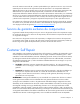
Customer self repair HP products are designed with many Customer Self Repair (CSR) parts to minimize repair time and allow for greater flexibility in performing defective parts replacement. If during the diagnosis period HP (or HP service providers or service partners) identifies that the repair can be accomplished by the use of a CSR part, HP will ship that part directly to you for replacement. There are two categories of CSR parts: • Mandatory—Parts for which customer self repair is mandatory.
• Obligatoire - Pièces pour lesquelles la réparation par le client est obligatoire. Si vous demandez à HP de remplacer ces pièces, les coûts de déplacement et main d'œuvre du service vous seront facturés. • Facultatif - Pièces pour lesquelles la réparation par le client est facultative. Ces pièces sont également conçues pour permettre au client d'effectuer lui-même la réparation.
NOTA: alcuni componenti HP non sono progettati per la riparazione da parte del cliente. Per rispettare la garanzia, HP richiede che queste parti siano sostituite da un centro di assistenza autorizzato. Tali parti sono identificate da un "No" nel Catalogo illustrato dei componenti. In base alla disponibilità e alla località geografica, le parti CSR vengono spedite con consegna entro il giorno lavorativo seguente.
anrufen und sich von einem Mitarbeiter per Telefon helfen lassen. Den Materialien, die mit einem CSRErsatzteil geliefert werden, können Sie entnehmen, ob das defekte Teil an HP zurückgeschickt werden muss. Wenn es erforderlich ist, das defekte Teil an HP zurückzuschicken, müssen Sie dies innerhalb eines vorgegebenen Zeitraums tun, in der Regel innerhalb von fünf (5) Geschäftstagen.
Centro de asistencia técnica de HP y recibirá ayuda telefónica por parte de un técnico. Con el envío de materiales para la sustitución de componentes CSR, HP especificará si los componentes defectuosos deberán devolverse a HP. En aquellos casos en los que sea necesario devolver algún componente a HP, deberá hacerlo en el periodo de tiempo especificado, normalmente cinco días laborables. Los componentes defectuosos deberán devolverse con toda la documentación relacionada y con el embalaje de envío.
periode, gewoonlijk vijf (5) werkdagen, retourneren aan HP. Het defecte onderdeel moet met de bijbehorende documentatie worden geretourneerd in het meegeleverde verpakkingsmateriaal. Als u het defecte onderdeel niet terugzendt, kan HP u voor het vervangende onderdeel kosten in rekening brengen. Bij reparatie door de klant betaalt HP alle verzendkosten voor het vervangende en geretourneerde onderdeel en kiest HP zelf welke koerier/transportonderneming hiervoor wordt gebruikt.
Serviço de garantia apenas para peças A garantia limitada da HP pode incluir um serviço de garantia apenas para peças. Segundo os termos do serviço de garantia apenas para peças, a HP fornece as peças de reposição sem cobrar nenhuma taxa. No caso desse serviço, a substituição de peças CSR é obrigatória. Se desejar que a HP substitua essas peças, serão cobradas as despesas de transporte e mão-de-obra do serviço.
Customer self repair 12
Customer self repair 13
Customer self repair 14
Customer self repair 15
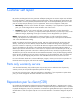
Illustrated parts catalog Mechanical components Item Description Spare part number Customer self repair (on page 5) 1 Access panel 413981-001 Mandatory1 2 Rack bezel 413983-001 Mandatory1 3 Front bezel, tower model 413982-001 Mandatory1 4 SATA/SAS hard drive cage, SFF 413985-001 Optional2 5 SATA/SAS hard drive cage, LFF* 413986-001 Optional2 Illustrated parts catalog 16
Item Description Spare part number Customer self repair (on page 5) 6 Hard drive blank, SFF 392613-001 Mandatory1 7 Hard drive blank, LFF* 389015-001 Mandatory1 8 Plastics/hardware kit 413989-001 Mandatory1 a) Removable media blank — — b) Retainer card guide — — c) Power supply blank — — d) Foot, carbonite* — — *Not shown 1 Mandatory—Parts for which customer self repair is mandatory.
HP realice su sustitución, puede o no conllevar costes adicionales, dependiendo del tipo de servicio de garantía correspondiente al producto. 3 No: No—Algunos componentes no están diseñados para que puedan ser reparados por el usuario. Para que el usuario haga valer su garantía, HP pone como condición que un proveedor de servicios autorizado realice la sustitución de estos componentes. Dichos componentes se identifican con la palabra “No” en el catálogo ilustrado de componentes.
System components Item Description Spare part number Customer self repair (on page 5) System components 9 Fan assembly, 92-mm 413978-001 Mandatory1 10 3-V lithium battery 234556-001 Mandatory1 11 Heatsink 413977-001 Optional2 12 Processor with thermal grease and alcohol pad — — a) Dual-Core, Intel® Xeon® Processor 5050 (3.00-GHz, 667MHz FSB, 4-MB cache)† 409423-001 Optional2 b) Dual-Core, Intel® Xeon® Processor 5060 (3.
Item Description Spare part number Customer self repair (on page 5) e) Dual-Core, Intel® Xeon® Processor 5120 (1.86-GHz, 1066MHz FSB, 1x4-MB L2 cache)*† 416794-001 Optional2 f) Dual-Core, Intel® Xeon® Processor 5130 (2.0-GHz, 1333MHz FSB, 1x4-MB L2 cache)*† 416796-001 Optional2 g) Dual-Core, Intel® Xeon® Processor 5140 (2.33-GHz, 1333MHz FSB, 1x4-MB L2 cache)*† 416797-001 Optional2 h) Dual-Core, Intel® Xeon® Processor 5150 (2.
Item 16 Description Spare part number Customer self repair (on page 5) a) System board with tray and screws, supports Intel® Xeon® 50xx and 51xx processors† 413984-001 Optional2 b) System board with tray and screws, supports Intel® Xeon® 52xx, 53xx, and 54xx processors*† 439399-001 Optional2 Power supply backplane 413144-001 Optional2 Mass storage devices 17 CD-ROM drive, PATA, 48X 397931-001 Mandatory1 18 CD-RW/DVD-ROM drive, PATA, 48X* 399404-001 Mandatory1 19 DVD-ROM drive, SATA, 1
Item Description Spare part number Customer self repair (on page 5) j) 500-GB, SATA, 7,200-rpm, LFF* 404654-001 Mandatory1 k) 1-TB, SATA, 7,200-rpm, LFF* 461289-001 Mandatory1 29 Parallel and second serial connector bracket* 418300-001 Mandatory1 30 Keyboard* 355630-001 Mandatory1 31 Mouse* 344704-001 Mandatory1 32 PCI-X expansion cage, two-slot assembly 439400-001 Optional2 33 Smart Array E200 Controller* 412799-001 Optional2 34 Smart Array E200 Controller cache module, 64-MB
Mandatory: Zwingend—Teile, die im Rahmen des Customer Self Repair Programms ersetzt werden müssen. Wenn Sie diese Teile von HP ersetzen lassen, werden Ihnen die Versand- und Arbeitskosten für diesen Service berechnet. 2 Optional: Optional—Teile, für die das Customer Self Repair-Verfahren optional ist. Diese Teile sind auch für Customer Self Repair ausgelegt.
Illustrated parts catalog 24
Removal and replacement procedures Required tools You need the following items for some procedures: • T-15 Torx screwdriver • Flathead screwdriver • Diagnostics Utility Safety considerations Before performing service procedures, review all the safety information. Preventing electrostatic discharge To prevent damaging the system, be aware of the precautions you need to follow when setting up the system or handling parts.
This symbol indicates the presence of electric shock hazards. The area contains no user or field serviceable parts. Do not open for any reason. WARNING: To reduce the risk of injury from electric shock hazards, do not open this enclosure. This symbol on an RJ-45 receptacle indicates a network interface connection. WARNING: To reduce the risk of electric shock, fire, or damage to the equipment, do not plug telephone or telecommunications connectors into this receptacle.
WARNING: To reduce the risk of personal injury or damage to the equipment, adequately stabilize the rack before extending a component outside the rack. Extend only one component at a time. A rack may become unstable if more than one component is extended. WARNING: When installing a server in a telco rack, be sure that the rack frame is adequately secured at the top and bottom to the building structure.
The system is now without power. Extend the server from the rack 1. Power down the server (on page 27). 2. Pull down the quick-release levers on each side of the server to release the server from the rack. IMPORTANT: If the server is installed in a telco rack, remove the server from the rack to access internal components. 3. Extend the server on the rack rails until the server rail-release latches engage.
Front bezel This server has a removable bezel that must be unlocked and opened before accessing the front panel components. The bezel should be kept closed during normal server operations. Use the key provided with the server to unlock the bezel with a clockwise turn. If necessary, remove the bezel. CAUTION: To avoid breaking the bezel, remove the bezel before placing the server on its side. For operations involving removable media bay access, the media bay panel can be removed from the bezel.
Tower foot To remove the component: 1. Power down the server (on page 27). 2. Remove the tower bezel ("Front bezel" on page 29). 3. Place the server on its side. 4. Remove the foot. To replace the component, reverse the removal procedure. Access panel CAUTION: Do not operate the server with the access panel removed. Operating the server in this manner results in improper airflow and improper cooling that can lead to thermal damage. To remove the component: 1. Power down the server (on page 27).
Rack bezel To remove the component: 1. Power down the server (on page 27). 2. Extend the server from the rack (on page 28). 3. Remove the access panel. 4. Remove the bezel. To replace the component, reverse the removal procedure. Rack rails NOTE: This procedure applies to rack servers only. To remove the component: 1. Power down the server (on page 27). 2. Remove the server from the rack (on page 28). 3. Use a flat-head screwdriver to lift the spring tab.
4. Slide the rail forward and remove it from the server. 5. Repeat the steps above to remove the other rail. To replace the component, reverse the removal procedure. Power supply blank Remove the blank from the bay. To replace the component, reverse the removal procedure. Hot-plug power supply WARNING: To reduce the risk of electric shock, do not disassemble the power supply or attempt to repair it. Replace it only with the specified spare part.
CAUTION: Do not attempt to remove and replace a power supply as a hot-plug procedure unless both bays are populated with power supplies. To remove the component: 1. Disconnect the power cord from the AC source. 2. Disconnect the power cord from the power supply. 3. Remove the power supply. CAUTION: To prevent improper cooling and thermal damage, do not operate the server unless all bays are populated with either a component or a blank. To replace the component, reverse the removal procedure.
NOTE: Depending on model purchased, the server may look slightly different than shown. To replace the component, reverse the removal procedure. Hot-plug SATA and SAS hard drives To remove the component: CAUTION: To prevent improper cooling and thermal damage, do not operate the server unless all bays are populated with either a component or a blank. 1. Determine the status of the hard drive from the hot-plug hard drive LEDs ("SAS and SATA hard drive LEDs" on page 80). 2.
3. Remove the hard drive. To replace the component, reverse the removal procedure. IMPORTANT: When installing a x3/x1 SAS cable in a SFF system, HP recommends that the x3 part of the x3/x1 cable be linked to the SAS hard drive backplane connector that corresponds to hard drive slots 1 to 4. In this setup, hard drive slot 1 will not be available, but since hard drive slots 2 to 4 will be connected, one continuous volume can be created. All drive slots will be available in LFF systems.
6. Remove the four T-15 screws and slide the hard drive cage out of the chassis. 7. Remove all hard drives. To replace the components, reverse the removal procedure. NOTE: When replacing or installing a 6-bay hard drive cage, connect the 10-pin power cable from the power backplane to the 8-pin power connector on the hard drive cage backplane. When seated properly, the connectors have a two-pin overlap. The overlap is cosmetic only and causes no functional side effects.
o Unlock and remove the bezel ("Front bezel" on page 29). o Extend the server from the rack (on page 28). 3. Remove the access panel. 4. Remove the air baffle. To replace the component, reverse the removal procedure. System fans CAUTION: The system fan is a non-hot-pluggable device. Fan failures are indicated by amber LEDs located on each hot-plug fan and by the front panel internal health LED.
6. Remove the fan. To replace the component, reverse the removal procedure. Expansion slot cover To remove the component: 1. Do one of the following: o Unlock and remove the bezel ("Front bezel" on page 29). o Extend the server from the rack (on page 28). 2. Remove the access panel. 3. Push the release latches on the expansion board retainer and open the retainer.
4. Remove the expansion slot cover. CAUTION: To prevent improper cooling and thermal damage, do not operate the server unless all PCI slots have either an expansion slot cover or an expansion board installed. To replace the component, reverse the removal procedure. Expansion board CAUTION: To prevent damage to the server or expansion boards, power down the server and remove all AC power cords before removing or installing the expansion boards. To remove the component: 1.
5. Push the release latches on the expansion board retainer and open the retainer. 6. Remove the T-15 Torx screw securing the expansion board, if necessary. 7. Remove the expansion board. To replace the component, reverse the removal procedure. Media bay blank To remove the component: 1. Open or remove the tower bezel ("Front bezel" on page 29). 2. Remove the access panel.
3. Remove the media bay blank. To replace the component, reverse the removal procedure. Battery-backed write cache module To remove the component: 1. Power down the server (on page 27). 2. Do one of the following: o Open or remove the tower bezel, as needed ("Front bezel" on page 29). o Extend the server from the rack (on page 28). 3. Remove the access panel. 4. Remove the cache module. To replace the component, reverse the removal procedure.
PCI-X expansion cage CAUTION: To prevent damage to the server or expansion boards, power down the server and remove all AC power cords before removing or installing the PCI expansion cage. To remove the component: 1. Power down the server. 2. Do one of the following: o Unlock and remove the bezel ("Front bezel" on page 29). o Extend the server from the rack (on page 28). 3. Remove the access panel. 4. Remove the rack bezel (rack servers only) ("Rack bezel" on page 31). 5.
8. Pull the spring-loaded locking pin out of its socket. 9. Remove the PCI-X expansion cage.
10. Remove any expansion boards. To replace the components, reverse the removal procedure. Half-height or full-height media device To remove the component: 1. Power down the server (on page 27). 2. Do one of the following: o Unlock and remove the bezel ("Front bezel" on page 29). o Extend the server from the rack (on page 28). 3. Remove the access panel. 4. Disconnect data and power cables.
o 5. SATA DVD-ROM drive Remove the device.
o Full-height To replace the component, reverse the removal procedure. IMPORTANT: Be sure to connect the right-angle end of the SATA data cable to the system board. Connecting it to the SATA drive may interfere with other installed media bay devices. IMPORTANT: If both SATA and PATA optical devices are installed simultaneously, only one can boot at a time. Boot priority will go to SATA if media is inserted into the SATA optical drive. Boot priority for PATA is not configurable.
6. Remove the heatsink. To replace the component: 1. Use the alcohol swab to remove all the existing thermal grease from the processor. Allow the alcohol to evaporate before continuing. 2. Remove the heatsink protective cover.
3. Install the heatsink. 4. Close the heatsink locking levers. 5. Connect the heatsink fan cable to the system board. 6. Install the access panel. 7. Do one of the following: 8. o Close or install the tower bezel, as needed. o Slide the server back into the rack. Power up the server. Processor IMPORTANT: If upgrading processor speed, update the system ROM before installing the processor.
IMPORTANT: PPM 2 must be installed when processor 2 is installed. The system fails to boot if the PPM is missing. CAUTION: To prevent possible server malfunction, do not mix processors of different speeds or cache sizes. Refer to the label on the processor heatsink for a description of the processor. IMPORTANT: Processor socket 1 must be populated at all times or the server does not function. CAUTION: Removal of the processor or heatsink renders the thermal layer between the processor and heatsink useless.
7. Using your fingers, remove the failed processor. To replace the component: IMPORTANT: Be sure the processor remains inside the processor installation tool. 1. If the processor has separated from the installation tool, carefully re-insert the processor in the tool. 2. Align the processor installation tool with the socket and install the spare processor. CAUTION: The processor is designed to fit one way into the socket.
3. Press down firmly until the processor installation tool clicks and separates from the processor, and then remove the processor installation tool.
4. Close the processor retaining latch and the processor socket retaining bracket. 5. Clean the old thermal grease from the heatsink with the alcohol swab. Allow the alcohol to evaporate before continuing. 6.
7. Install the heatsink. 8. Close the heatsink locking levers 9. Connect the heatsink fan cable to the system board. 10. Install the access panel. 11. Do one of the following: 12. o Close or install the tower bezel, as needed. o Slide the server back into the rack. Power up the server. PPM NOTE: PPM 1 is embedded in the system board.
To remove the component: 1. Power down the server (on page 27). 2. Do one of the following: o Unlock and remove the bezel ("Front bezel" on page 29). o Extend the server from the rack (on page 28). 3. Remove the access panel. 4. Open the PPM latches. 5. Remove the PPM. NOTE: The appearance of compatible PPMs may vary. To replace the component, reverse the removal procedure. FBDIMM To remove the component: 1. Power down the server (on page 27). 2.
5. Remove the redundant fan, if applicable. 6. Remove the FBDIMM. To replace the component, reverse the removal procedure. Parallel and second serial connector bracket To remove the component: 1. Power down the server (on page 27). 2. Do one of the following: o Unlock and remove the bezel ("Front bezel" on page 29). o Extend the server from the rack (on page 28). 3. Remove the access panel. 4. Push the release latches on the expansion board retainer and open the retainer.
5. Remove the T-15 Torx screw securing the parallel and second serial connector bracket. 6. Remove the parallel and second serial connector bracket. To replace the component, reverse the removal procedure. Battery If the server no longer automatically displays the correct date and time, you may need to replace the battery that provides power to the real-time clock. Under normal use, battery life is 5 to 10 years.
4. Remove the battery. IMPORTANT: Replacing the system board battery resets the system ROM to its default configuration. After replacing the battery, reconfigure the system through RBSU. To replace the component, reverse the removal procedure. For more information about battery replacement or proper disposal, contact an authorized reseller or an authorized service provider. System board To remove the component: 1. Power down the server (on page 27). 2.
CAUTION: To avoid damage to the system board: • Do not touch the processor socket contacts. • Always install the processor socket cover after removing the processor from the socket. • Do not tilt or slide the processor when lowering the processor into the socket. CAUTION: Removal of the processor or heatsink renders the thermal layer between the processor and heatsink useless. Clean the component with the provided alcohol swab, then add thermal grease. 11.
CAUTION: To avoid damage to the system board: • Do not touch the processor socket contacts. • Always install the processor socket cover after removing the processor from the socket. • Do not tilt or slide the processor when lowering the processor into the socket. 13. Disconnect all cables connected to the system board. 14. Loosen the two system board thumbscrews. 15. Using the system board tray handles, slide the tray forward and remove the failed system board. To replace the component: 1.
a. Open the processor retaining latch and the processor socket retaining bracket. b. Remove the processor socket protective cover. 3. Install the processor socket cover onto the processor socket of the failed system board. 4. Install the processor on the spare system board. CAUTION: The processor is designed to fit one way into the socket. Use the alignment guides on the processor and socket to properly align the processor with the socket. Refer to the server hood label for specific instructions.
5. Close the processor retaining latch and the processor socket retaining bracket. 6. Clean the old thermal grease from the heatsink and the top of the processor with the alcohol swab. Allow the alcohol to evaporate before continuing.
7. Apply all the grease to the top of the processor in one of the following patterns to ensure even distribution: 8. Install the heatsink.
9. Close the heatsink locking levers. 10. Connect the heatsink fan cable to the system board. IMPORTANT: Install all components with the same configuration that was used on the failed system board. 11. Install all components removed from the failed system board. 12. Install the access panel. 13. Do one of the following: 14. o Install and lock the bezel. o Slide the server back into the rack. Power up the server.
Power supply backplane To remove the component: 1. Power down the server (on page 27). 2. Remove the power supplies ("Hot-plug power supply" on page 32). 3. Do one of the following: o Unlock and remove the bezel ("Front bezel" on page 29). o Extend the server from the rack (on page 28). 4. Remove the access panel. 5. Remove the air baffle ("Air baffle" on page 36). 6. Remove the system fans (on page 37). 7. Remove all expansion boards ("Expansion board" on page 39).
Cabling Optional SATA or SAS cabling Many configurations are possible when SATA or SAS controllers are added. When upgrading the storage controller, refer to the Quickspecs and the cabling matrix to identify the correct cables (http://h10010.www1.hp.com/wwpc/pscmisc/vac/us/en/ss/proliant/proliant-ml.html).
• PATA optical drive cabling • SATA optical drive cabling Optional ATA or ATAPI device cabling This server includes one PATA cable (the Cable Select Cable) that can connect up to two ATA or ATAPI devices to the system through the integrated PATA controller. This cable has three clearly labeled connectors. If only one PATA device is connected to the system, it must be secured to the cable connector labeled Drive 0. For all PATA devices, set the configuration jumpers to "Cable Select" or "CS.
Diagnostic tools Troubleshooting resources The HP ProLiant Servers Troubleshooting Guide provides procedures for resolving common problems and comprehensive courses of action for fault isolation and identification, error message interpretation, issue resolution, and software maintenance on ProLiant servers and server blades. This guide includes problemspecific flowcharts to help you navigate complex troubleshooting processes. To view the guide, select a language: • English (http://www.hp.
For additional information, refer to the Management CD in the HP ProLiant Essentials Foundation Pack or the HP SIM website (http://www.hp.com/go/hpsim). Integrated Management Log The IML records hundreds of events and stores them in an easy-to-view form. The IML timestamps each event with 1-minute granularity.
For more information regarding array controller configuration, refer to the controller user guide. For more information regarding the default configurations that ORCA uses, refer to the HP ROM-Based Setup Utility User Guide on the Documentation CD. HP ProLiant Essentials Rapid Deployment Pack The RDP software is the preferred method for rapid, high-volume server deployments. The RDP software integrates two powerful products: Altiris Deployment Solution and the HP ProLiant Integration Module.
• Access advanced troubleshooting features through the iLO 2 interface. • Diagnose iLO 2 using HP SIM through a web browser and SNMP alerting. For more information about iLO 2 features, refer to the iLO 2 documentation on the Documentation CD or on the HP website (http://www.hp.com/servers/lights-out).
HP Insight Diagnostics HP Insight Diagnostics is a proactive server management tool, available in both offline and online versions, that provides diagnostics and troubleshooting capabilities to assist IT administrators who verify server installations, troubleshoot problems, and perform repair validation. HP Insight Diagnostics Offline Edition performs various in-depth system and component testing while the OS is not running. To run this utility, launch the SmartStart CD.
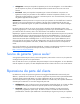
Component identification Front panel components Item Description 1 Removable media bays (4) 2 CD-ROM drive 3 Hot-plug hard drive bays (8-bay drive cage model) 4 Hot-plug hard drive bays (6-bay drive cage model) 5 USB connectors (2) Component identification 72
Front panel LEDs and buttons Item Description Status 1 Power On/Standby button — 2 System power LED Green = Power on Amber = System shut down, but power still applied Off = No power 3 Internal health LED Green = Normal Amber = System degraded. To identify the component in a degraded state, refer to system board LEDs. Red = System critical. To identify the component in a critical state, refer to system board LEDs.
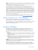
Rear panel components Item Description 1 Video connector 2 Serial connector 3 USB connectors (2) 4 RJ-45 Ethernet connector (iLO 2 management) 5 RJ-45 Ethernet connector (data) 6 PCI Express x8 slots (x4 routed) 7 PCI-X slots (100-MHz) 8 PCI-X slot (133-MHz) 9 Optional redundant hot-plug power supply bay 10 Mouse connector 11 Keyboard connector 12 Power cord connector Component identification 74
Rear panel LEDs and buttons Item Description Status 1 Power supply LED Green = Power supply is on and functioning Off = No power or inadequate power supply 2 UID LED and button Blue = Activated Flashing blue = Remote inquiry Off = Deactivated 3 iLO 2 activity LED Green or flashing = Network activity Off = No network activity 4 iLO 2 link LED Green = Linked to network Off = Not linked to network 5 6 10/100/1000 NIC activity LED Green or flashing = Network activity 10/100/1000 NIC link LED
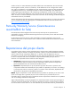
System board components NOTE: PPM 1 is embedded in the system board.
Item Description 22 PCI Express x8 slots 4-6 (x4 routed) 23 PPM 2 slot 24 Optional redundant system fan 4 connector 25 System fan 2 connector 26 Optional redundant system fan 3 connector 27 System fan 1 connector 28 FBDIMM slots NMI jumper The NMI jumper allows administrators to perform a memory dump before performing a hard reset. Crash dump analysis is an essential part of eliminating reliability problems, such as hangs or crashes in operating systems, device drivers, and applications.
System board LEDs Item Description Status 1 FBDIMM 1-8 Amber = FBDIMM failed Off = FBDIMM functioning 2 Processor 1 Amber = Processor 1 failed Off = Processor 1 functioning 3 4 Processor 1 fan failure (fan 5) Amber = Fan is not installed or has failed PPM 1 (embedded) Amber = PPM 1 failed Off = Processor fan is functioning Off = PPM 1 functioning 5 Processor 2 Amber = Processor 2 failed Off = Processor 2 functioning 6 AC power Green = Power supply is on and functioning Off = No AC power
Item Description Status 12 Optional redundant system fan 2 Amber = Redundant fan has failed System fan 1 Amber = Fan is not installed or has failed 13 Off = Redundant fan is functioning Off = Rear fan is functioning 14 Online spare memory Amber = Online spare memory is in use due to memory failover Off = Normal operation 15 Memory mode Green = System is in online spare memory mode Off = Normal operation System LEDs and internal health LED combinations When the internal health LED on the fron
System LED and color Internal health LED color Status Overtemperature (amber) Red • The Health Driver has detected a cautionary temperature level. • The server has detected a hardware critical temperature level. Fan (amber) Red The minimum fan requirements are not being met. Fan has failed. Amber A fan has failed but still meets the minimum fan requirements (with redundant fan option only).
Online/activity LED (green) Fault/UID LED (amber/blue) Interpretation Flashing regularly (1 Hz) Amber, flashing regularly (1 Hz) Do not remove the drive. Removing a drive may terminate the current operation and cause data loss. The drive is part of an array that is undergoing capacity expansion or stripe migration, but a predictive failure alert has been received for this drive. To minimize the risk of data loss, do not replace the drive until the expansion or migration is complete.
Specifications Environmental specifications Specification Value Temperature range* Operating 10°C to 35°C (50°F to 95°F) Shipping -40°C to 70°C (-40°F to 158°F) Maximum wet bulb temperature 28°C (82.4°F) Relative humidity (noncondensing)** Operating 10% to 90% Non-operating 5% to 95% * All temperature ratings shown are for sea level. An altitude derating of 1°C per 300 m (1.8°F per 1,000 ft) to 3048 m (10,000 ft) is applicable. No direct sunlight allowed.
Specification Value Maximum peak power 1000 W (low line), 1200 W (high line) Rack server specifications Specification Value Dimensions Height 21.7 cm (8.54 in) Depth (with bezel) 55.7 cm (21.9 in) Width (with bezel) 44.5 cm (17.5 in) Weight (no drives installed) 27.
Specification Value Drive rotation 300 rpm Transfer rate High 500 Kb/s Low 250 Kb/s Bytes/sector 512 Sectors per track (high/low) 18/9 Tracks per side (high/low) 80/80 Access times Track-to-track (high/low) 3 ms/6 ms Average (high/low) 169 ms/94 ms Setting time 15 ms Latency average 100 ms Cylinders (high/low) 80/80 Read/write heads 2 FBDIMM specifications CAUTION: Be sure to install FBDIMMs in the proper configuration. Refer to the Documentation CD.
Specification Value Height 41 mm (1.6 in) Depth 172 mm (6.7 in) Width 147 mm (5.8 in) Weight 1 kg (2.2 lb) Data transfer rate Sustained 150 KB/s (sustained 1X), 1500/3600 KB/s (10X to 24X) Burst 16.6 MB/s Access times (typical) Full stroke 300 ms Random 140 ms Diameter 12 cm, 8 cm (4.70 in, 3.15 in) Thickness 1.2 mm (0.05 in) Track pitch 1.6 µm (6.
Specification Value Width 147 mm (5.8 in) Weight 1 kg (2.2 lb) Data transfer rate Sustained 4463 - 10,800 KB/s (8X CAV DVD mode), 150 KB/s (sustained 1X CD-ROM), 1500 - 7200 KB/s (10X - 48X CAV) Burst 150 MB/s Access times (typical) Full stroke <210 ms CD <250 ms DVD Random <125 ms CD <140 ms DVD Diameter 12 cm, 8 cm (4.70 in, 3.15 in) Thickness 1.2 mm (0.05 in) Track pitch 0.74 µm (3.15 × 10⁻⁷ in) DVD-ROM 1.6 µm (6.
Acronyms and abbreviations ABEND abnormal end ASR Automatic Server Recovery ATA Advanced Technology Attachment ATAPI Advanced Technology Attachment Packet Interface BIOS Basic Input/Output System DDR double data rate FBDIMM fully buffered DIMM iLO 2 Integrated Lights-Out 2 IML Integrated Management Log ISEE Instant Support Enterprise Edition LED light-emitting diode NIC network interface controller Acronyms and abbreviations 87
NMI non-maskable interrupt NVRAM non-volatile memory ORCA Option ROM Configuration for Arrays PATA parallel ATA PCI Express Peripheral Component Interconnect Express PCI-X peripheral component interconnect extended PPM processor power module RAID redundant array of inexpensive (or independent) disks RBSU ROM-Based Setup Utility RDP Rapid Deployment Pack ROM read-only memory SAS serial attached SCSI SATA serial ATA SFF small form-factor Acronyms and abbreviations 88
SIM Systems Insight Manager UID unit identification USB universal serial bus Acronyms and abbreviations 89
Index A F air baffle 36 Altiris Deployment Solution 69 Altiris eXpress Deployment Server 69 Autorun menu 70 fans 37 FBDIMMs 54, 77, 84 features 72 front bezel 29, 31 front panel components 72 front panel LEDs 73 full-height media drive 44 B battery 56 BIOS upgrade 69 blanks 32, 33, 40 buttons 72, 73 C cables 65, 66 cabling 65, 66 CD-ROM drive 44, 72, 84 component identification 72, 74, 80 components 16, 19, 72, 74 configuration of system 69 connectors 72, 73, 74 creating a disk image 69 CSR (customer s
M management tools 67 mechanical components 16 media devices 44, 65 N NIC LEDs 72, 73, 75, 79 NMI jumper 77 O Online ROM Flash Component Utility 70 Option ROM Configuration for Arrays (ORCA) 68 ORCA (Option ROM Configuration for Arrays) 68 P parallel connector 55, 74 part numbers 16, 19 PATA optical drive 44, 65 power LEDs, system 72, 73 Power On/Standby button 27, 72, 73 power requirements 83 power supplies 32, 83 power supply backplane 64 power supply blank 32 powering down 27 PPM (processor power modu