HP 1:10Gb Ethernet BL-c Switch for c-Class BladeSystem Application Guide Part number: 445881-001 First edition: April 2007
Legal notices © 2007 Hewlett-Packard Development Company, L.P. The information contained herein is subject to change without notice. The only warranties for HP products and services are set forth in the express warranty statements accompanying such products and services. Nothing herein should be construed as constituting an additional warranty. HP shall not be liable for technical or editorial errors or omissions contained herein. Microsoft®, Windows®, and Windows NT® are U.S.
Contents Contents Accessing the switch Introduction ........................................................................................................................................... 9 Additional references ........................................................................................................................... 10 Typographical conventions.................................................................................................................... 10 Management Network.....
Contents User access control .............................................................................................................................. 34 Setting up user IDs .......................................................................................................................... 35 Ports and trunking Introduction ......................................................................................................................................... 36 Ports on the switch .............
Contents Introduction ......................................................................................................................................... 66 Overview............................................................................................................................................ 66 Bridge Protocol Data Units .................................................................................................................... 66 Determining the path for forwarding BPDUs.........
Contents Using ACL Groups ............................................................................................................................... 88 ACL Metering and Re-marking ............................................................................................................... 89 Metering ........................................................................................................................................ 89 Re-marking ....................................................
Contents Configuring Configuring Configuring Configuring Configuring Configuring IGMP Snooping (CLI example) ................................................................................. 119 IGMP Filtering (CLI example).................................................................................... 120 a Static Mrouter (CLI example) ................................................................................. 120 IGMP Snooping (BBI example) ......................................................
Contents High availability Introduction ....................................................................................................................................... 164 Uplink Failure Detection ...................................................................................................................... 164 Failure Detection Pair..................................................................................................................... 165 Spanning Tree Protocol with UFD ........
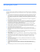
Accessing the switch Accessing the switch Introduction This guide will help you plan, implement, and administer the switch software for the HP 1:10Gb Ethernet BL-c Switch. Where possible, each section provides feature overviews, usage examples, and configuration instructions. • “Accessing the switch” describes how to configure and view information and statistics on the switch over an IP network.
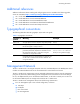
Accessing the switch Additional references Additional information about installing and configuring the switch is available in the following guides, which are available at http://www.hp.com/go/bladesystem/documentation.
Accessing the switch ○ Untagged ○ Port VLAN ID (PVID): 4095 • VLAN 4095—Management VLAN 4095 isolates management traffic within the HP 1:10GbE switch. VLAN 4095 contains only one member port (port 18). No other ports can be members of VLAN 4095. • Interface 256—Management interface 256 is associated with VLAN 4095. No other interfaces can be associated with VLAN 4095. You can configure the IP address of the management interface manually or through Dynamic Host Control Protocol (DHCP).
Accessing the switch Using the command line interfaces The command line interface (CLI) can be accessed via local terminal connection or a remote session using Telnet or SSH. The CLI is the most direct method for collecting switch information and performing switch configuration. The HP 1:10GbE switch provides two CLI modes: The menu-based AOS CLI, and the tree-based ISCLI. You can set the HP 1:10GbE switch to use either CLI mode.
Accessing the switch The following example shows how to manually configure an IP address on the switch: 1. Configure an IP interface for the Telnet connection, using the sample IP address of 205.21.17.3. 2. The pending subnet mask address and broadcast address are automatically calculated. >> # /cfg/l3/if 1 (Select IP interface 1) >> IP Interface 1# addr 205.21.17.3 (Assign IP address for the interface) Current IP address: 0.0.0.0 New pending IP address: 205.21.17.3 Pending new subnet mask: 255.255.255.0 .
Accessing the switch Using Simple Network Management Protocol The switch software provides SNMP v1.0 and SNMP v3.0 support for access through any network management software, such as HP-OpenView. SNMP v1.0 To access the SNMP agent on the switch, the read and write community strings on the SNMP manager should be configured to match those on the switch. The default read community string on the switch is public and the default write community string is private.
Accessing the switch User configuration Users can be configured to use the authentication/privacy options. The HP 1:10GbE switch supports two authentication algorithms: MD5 and SHA, as specified in the following command: /cfg/sys/ssnmp/snmpv3/usm /auth md5|sha 1.
Accessing the switch View based configurations CLI user equivalent To configure an SNMP user equivalent to the CLI user, use the following configuration: /c/sys/ssnmp/snmpv3/usm 4 name "usr" /c/sys/ssnmp/snmpv3/access 3 name "usrgrp" rview "usr" wview "usr" nview "usr" /c/sys/ssnmp/snmpv3/group 4 uname usr gname usrgrp /c/sys/ssnmp/snmpv3/view 6 name "usr" tree " 1.3.6.1.4.1.11.2.3.7.11.33.1.2.1.2" /c/sys/ssnmp/snmpv3/view 7 name "usr" tree " 1.3.6.1.4.1.11.2.3.7.11.33.1.2.1.
Accessing the switch CLI oper equivalent To configure an SNMP user equivalent to the CLI oper, use the following configuration: /c/sys/ssnmp/snmpv3/usm 5 name "oper" /c/sys/ssnmp/snmpv3/access 4 name "opergrp" rview "oper" wview "oper" nview "oper" /c/sys/ssnmp/snmpv3/group 4 uname oper gname opergrp /c/sys/ssnmp/snmpv3/view 20 name "oper" tree " 1.3.6.1.4.1.11.2.3.7.11.33.1.2.1.2" /c/sys/ssnmp/snmpv3/view 21 name "oper" tree " 1.3.6.1.4.1.11.2.3.7.11.33.1.2.1.
Accessing the switch 3. Configure an entry in the notify table. /c/sys/ssnmp/snmpv3/notify 10 name v1trap tag v1trap (Assign user to the notify table) 4. Specify the IP address and other trap parameters in the Target Address( targetAddr) and Target Parameters (targetParam) tables. Use the following command to specify the user name used with this targetParam table: c/sys/ssnmp/snmpv3/tparam /uname /c/sys/ssnmp/snmpv3/taddr 10 name v1trap addr 47.80.23.
Accessing the switch SNMPv2 trap host configuration The SNMPv2 trap host configuration is similar to the SNMPv1 trap host configuration. Wherever you specify the model, specify snmpv2 instead of snmpv1. c/sys/ssnmp/snmpv3/usm 10 name "v2trap" /c/sys/ssnmp/snmpv3/access 10 name "v2trap" model snmpv2 nview "iso" /c/sys/ssnmp/snmpv3/group 10 model snmpv2 uname v2trap gname v2trap /c/sys/ssnmp/snmpv3/notify 10 name v2trap tag v2trap /c/sys/ssnmp/snmpv3/taddr 10 name v2trap addr 47.81.25.
Accessing the switch The following example shows how to configure a SNMPv3 user v3trap with authentication only: /c/sys/ssnmp/snmpv3/usm 11 name "v3trap" auth md5 authpw v3trap /c/sys/ssnmp/snmpv3/access 11 name "v3trap" level authNoPriv nview "iso" /c/sys/ssnmp/snmpv3/group 11 uname v3trap gname v3trap /c/sys/ssnmp/snmpv3/notify 11 name v3trap tag v3trap /c/sys/ssnmp/snmpv3/taddr 11 name v3trap addr 47.81.25.
Accessing the switch Configuring an IP address range for the management network Configure the management network IP address and mask from the System Menu in the CLI. For example: >> Main# /cfg/sys/access/mgmt/add Enter Management Network Address: 192.192.192.0 Enter Management Network Mask: 255.255.255.128 In this example, the management network is set to 192.192.192.0 and management mask is set to 255.255.255.128. This defines the following range of allowed IP addresses: 192.192.192.1 to 192.192.192.
Accessing the switch Configuring RADIUS on the switch (CLI example) To configure RADIUS on the switch, do the following: 1. Turn RADIUS authentication on, and then configure the Primary and Secondary RADIUS servers. For example: >> Main# /cfg/sys/radius (Select the RADIUS Server menu) >> RADIUS Server# on (Turn RADIUS on) Current status: OFF New status: ON >> RADIUS Server# prisrv 10.10.1.1 (Enter primary server IP) Current primary RADIUS server: 0.0.0.0 New pending primary RADIUS server: 10.10.1.
Accessing the switch Configuring RADIUS on the switch (BBI example) 1. Configure RADIUS parameters. a. Click the Configure context button. b. Open the System folder, and select Radius. c. Enter the IP address of the primary and secondary RADIUS servers, and enter the RADIUS secret for each server. Enable the RADIUS server. CAUTION: If you configure the RADIUS secret using any method other than a direct console connection, the secret may be transmitted over the network as clear text. d. Click Submit.
Accessing the switch 2. Apply, verify, and save the configuration. RADIUS authentication features The switch supports the following RADIUS authentication features: • Supports RADIUS client on the switch, based on the protocol definitions in RFC 2138 and RFC 2866. • • Allows RADIUS secret password up to 32 bytes.
Accessing the switch Table 2 User access levels User account Description and tasks performed Administrator Administrators are the only ones that can make permanent changes to the switch configuration—changes that are persistent across a reboot/reset of the switch. Administrators can access switch functions to configure and troubleshoot problems on the switch level.
Accessing the switch TACACS+ offers the following advantages over RADIUS: • TACACS+ uses TCP-based connection-oriented transport; whereas RADIUS is UDP based. TCP offers a connection-oriented transport, while UDP offers best-effort delivery. RADIUS requires additional programmable variables such as re-transmit attempts and time-outs to compensate for best-effort transport, but it lacks the level of built-in support that a TCP transport offers.
Accessing the switch Alternate mapping between TACACS+ privilege levels and switch management access levels is shown in the table below. Use the command /cfg/sys/tacacs/cmap ena to use the alternate TACACS+ privilege levels. Table 5 Alternate TACACS+ privilege levels User access level TACACS+ level user 0—1 oper 6—8 admin 14—15 You can customize the mapping between TACACS+ privilege levels and HP 1:10GbE switch management access levels.
Accessing the switch Configuring TACACS+ authentication on the switch (CLI example) 1. Turn TACACS+ authentication on, and then configure the Primary and Secondary TACACS+ servers. >> Main# /cfg/sys/tacacs (Select the TACACS+ Server menu) >> TACACS+ Server# on (Turn TACACS+ on) Current status: OFF New status: ON >> TACACS+ Server# prisrv 10.10.1.1 (Enter primary server IP) Current primary TACACS+ server: 0.0.0.0 New pending primary TACACS+ server: 10.10.1.1 >> TACACS+ Server# secsrv 10.10.1.
Accessing the switch Configuring TACACS+ authentication on the switch (BBI example) 1. Configure TACACS+ authentication for the switch. a. Click the Configure context button. b. Open the System folder, and select Tacacs+. c. Enter the IP address of the primary and secondary TACACS+ servers, and enter the TACACS+ secret. Enable TACACS+. d. Click Submit.
Accessing the switch e. Configure custom privilege-level mapping (optional). Click Submit to accept each mapping change. 2. Apply, verify, and save the configuration. Secure Shell and Secure Copy Secure Shell (SSH) and Secure Copy (SCP) use secure tunnels to encrypt and secure messages between a remote administrator and the switch. Telnet does not provide this level of security. The Telnet method of managing a switch does not provide a secure connection.
Accessing the switch The switch implementation of SSH is based on version 1.5 and version 2.0, and supports SSH clients from version 1.0 through version 2.0. Client software can use SSH version 1 or version 2. The following SSH clients are supported: • • • • • SSH 3.0.1 for Linux (freeware) SecureCRT® 4.1.8 (VanDyke Technologies, Inc.) OpenSSH_3.9 for Linux (FC 3) FedoraCore 3 for SCP commands PuTTY Release 0.
Accessing the switch Configuring the SCP administrator password To configure the scpadmin (SCP administrator) password, first connect to the switch via the RS-232 management console. For security reasons, the scpadmin password can be configured only when connected directly to the switch console. To configure the password, enter the following CLI command. At factory default settings, the current SCP administrator password is admin.
Accessing the switch Applying and saving configuration Enter the apply and save commands after the command above (scp ad4.cfg 205.178.15.157:putcfg), or use the following commands. You will be prompted for a password. >> # scp @:putcfg_apply >> # scp @:putcfg_apply_save For example: >> # scp ad4.cfg admin@205.178.15.157:putcfg_apply >> # scp ad4.cfg admin@205.178.15.
Accessing the switch A value of 0 denotes that RSA server key autogeneration is disabled. When greater than 0, the switch will auto generate the RSA server key every specified interval; however, RSA server key generation is skipped if the switch is busy doing other key or cipher generation when the timer expires. The switch will perform only one session of key/cipher generation at a time.
Accessing the switch Setting up user IDs The administrator can configure up to 10 user accounts. To configure an end-user account, perform the following steps: 1. Select a user ID to define. >> # /cfg/sys/access/user/uid 1 2. Define the user name and password. >> User ID 1 # name jane Current user name: New user name: jane (Assign name “jane” to user ID 1) 3. Define the user access level. By default, the end user is assigned to the user access level.
Ports and trunking Ports and trunking Introduction The first part of this chapter describes the different types of ports used on the switch. This information is useful in understanding other applications described in this guide, from the context of the embedded switch/server environment. For specific information on how to configure ports for speed, auto-negotiation, and duplex modes, see the port commands in the HP 1:10Gb Ethernet BL-c Switch Command Reference.
Ports and trunking Table 7 Ethernet switch port names Port number Port alias 13 Downlink13 14 Downlink14 15 Downlink15 16 Downlink16 17 XConnect1 18 Mgmt 19 Uplink1 20 Uplink2 21 Uplink3 22 Uplink4 23 Uplink5 24 Uplink6 25 Uplink7 Port trunk groups When using port trunk groups between two switches, you can create an aggregate link operating at up to five Gigabits per second, depending on how many physical ports are combined.
Ports and trunking Before you configure trunks When you create and enable a trunk, the trunk members (switch ports) take on certain settings necessary for correct operation of the trunking feature. Before you configure your trunk, you must consider these settings, along with specific configuration rules, as follows: 1. Read the configuration rules provided in the “Trunk group configuration rules” section. 2.
Ports and trunking Port trunking example In this example, the Gigabit uplink ports on each switch are configured into a total of four trunk groups: two on each switch. NOTE: The actual mapping of switch ports to NIC interfaces is dependant on the operating system software, the type of server blade, and the enclosure type. For more information, see the HP 1:10Gb Ethernet BL-c Switch User Guide.
Ports and trunking Configuring trunk groups (CLI example) 1.
Ports and trunking Configuring trunk groups (BBI example) 1. Configure trunk groups. a. Click the Configure context button on the Toolbar. b. Open the Layer 2 folder, and select Trunk Groups. c. Click a Trunk Group number to select it.
Ports and trunking d. Enable the Trunk Group. To add ports, select each port in the Ports Available list, and click Add. e. Click Submit. 2. Apply, verify, and save the configuration. 3. Examine the trunking information on each switch. a. Click the Dashboard context button on the Toolbar.
Ports and trunking b. Select Trunk Groups. c. Information about each configured trunk group is displayed. Make sure that trunk groups consist of the expected ports and that each port is in the expected state. Configurable Trunk Hash algorithm This feature allows you to configure the particular parameters for the HP 1:10GbE switch Trunk Hash algorithm instead of having to utilize the defaults. You can configure new default behavior for Layer 2 traffic and Layer 3 traffic, using the CLI menu cfg/l2/thash.
Ports and trunking Link Aggregation Control Protocol Link Aggregation Control Protocol (LACP) is an IEEE 802.3ad standard for grouping several physical ports into one logical port (known as a dynamic trunk group or Link Aggregation group) with any device that supports the standard. Refer to the IEEE 802.3ad-2002 for a full description of the standard. The 802.3ad standard allows standard Ethernet links to form a single Layer 2 link using the Link Aggregation Control Protocol (LACP).
Ports and trunking Each port in the HP 1:10GbE switch can have one of the following LACP modes. • • • off (default)—The user can configure this port in to a regular static trunk group. active—The port is capable of forming an LACP trunk. This port sends LACPDU packets to partner system ports. passive—The port is capable of forming an LACP trunk. This port only responds to the LACPDU packets sent from an LACP active port.
Port-based Network Access and traffic control Port-based Network Access and traffic control Port-based Network Access control Port-based Network Access control provides a means of authenticating and authorizing devices attached to a LAN port that has point-to-point connection characteristics. It prevents access to ports that fail authentication and authorization. This feature provides security to all ports of the HP 1:10GbE switch (except the management port 18).
Port-based Network Access and traffic control 802.1x authentication process The clients and authenticators communicate using Extensible Authentication Protocol (EAP), which was originally designed to run over PPP, and for which the IEEE 802.1x Standard has defined an encapsulation method over Ethernet frames, called EAP over LAN (EAPOL). The following figure shows a typical message exchange initiated by the client.
Port-based Network Access and traffic control The Radius server chooses an EAP-supported authentication algorithm to verify the client’s identity, and sends an EAP-Request packet to the client via the switch authenticator. The client then replies to the Radius server with an EAP-Response containing its credentials. Upon a successful authentication of the client by the server, the 802.
Port-based Network Access and traffic control Table 9 EAP support for RADIUS attributes # Attribute Attribute Value A-R A-A A-C A-R 24 State Server-specific value. This is sent unmodified back to the server in an Access-Request that is in response to an Access-Challenge. 0-1 0-1 0-1 0 30 Called-Station-ID The MAC address of the authenticator encoded as an ASCII string in canonical format, e.g. 000D5622E3 9F.
Port-based Network Access and traffic control • The 802.1x standard has optional provisions for supporting dynamic virtual LAN assignment via RADIUS tunneling attributes, for example, Tunnel-Type (=VLAN), Tunnel-Medium-Type (=802), and Tunnel-Private-Group-ID (=VLAN id). These attributes are not supported and might affect 802.1x operations. Other unsupported attributes include Service-Type, Session-Timeout, and TerminationAction. RADIUS accounting service for 802.
VLANs VLANs Introduction This chapter describes network design and topology considerations for using Virtual Local Area Networks (VLANs). VLANs are commonly used to split up groups of network users into manageable broadcast domains, to create logical segmentation of workgroups, and to enforce security policies among logical segments.
VLANs Viewing VLANs The VLAN information menu (/info/l2/vlan) displays all configured VLANs and all member ports that have an active link state, for example: >> Layer 2# vlan VLAN Name Status Ports ---- -------------------------------- ------ ---------------------1 Default VLAN ena 1 4-18 19-25 2 VLAN 2 ena 2 3 4095 VLAN 4095 ena 18 PVID numbers Each port in the switch has a configurable default VLAN number, known as its PVID.
VLANs VLAN tagging The switch supports IEEE 802.1Q VLAN tagging, providing standards-based VLAN support for Ethernet systems. Tagging places the VLAN identifier in the frame header, allowing each port to belong to multiple VLANs. When you configure multiple VLANs on a port, you must also enable tagging on that port.
VLANs Figure 3 Default VLAN settings NOTE: The port numbers specified in these illustrations may not directly correspond to the physical port configuration of your switch model. When you configure VLANs, you configure the switch ports as tagged or untagged members of specific VLANs. See the following figures. In the following figure, the untagged incoming packet is assigned directly to VLAN 2 (PVID = 2).
VLANs Figure 5 802.1Q tagging (after port-based VLAN assignment) In the following figure, the tagged incoming packet is assigned directly to VLAN 2 because of the tag assignment in the packet. Port 5 is configured as a tagged member of VLAN 2, and port 7 is configured as an untagged member of VLAN 2. Figure 6 802.1Q tag assignment As shown in the following figure, the tagged packet remains unchanged as it leaves the switch through port 5, which is configured as a tagged member of VLAN 2.
VLANs Figure 7 802.1Q tagging (after 802.1Q tag assignment) NOTE: Using the /boot/conf factory command resets all ports to VLAN 1 (except management port 18) and all other settings to the factory defaults at the next reboot. VLANs and IP interfaces Carefully consider how you create VLANs within the switch, so that communication with the switch remains possible.
VLANs VLAN configuration rules VLANs operate according to specific configuration rules which must be considered when creating VLANs. For example: • HP recommends that all ports involved in trunking and Port Mirroring have the same VLAN configuration. If a port is on a trunk with a mirroring port, the VLAN configuration cannot be changed. For more information on port trunking, see the “Port trunking example” section in the “Ports and trunking” chapter.
VLANs Figure 8 Multiple VLANs with VLAN tagging The features of this VLAN are described in the following table: Table 10 Multiple VLANs with tagging Component Description Switch 1 Switch 1 is configured for VLANS 1, 2, and 3. Port 1 is tagged to accept traffic from VLANs 1 and 2. Port 17 is tagged, and accepts traffic from VLANs 1 and 3. Port 19 is tagged to accept traffic from VLANs 1, 2, and 3. Port 21 is an untagged member of VLAN 2. Switch 2 Switch 2 is configured for VLANS 1, 3, and 4.
VLANs Table 10 Multiple VLANs with tagging Component Description Blade Server #1 This high-use blade server needs to be accessed from all VLANs and IP subnets. The server has a VLAN-tagging adapter installed with VLAN tagging turned on. One adapter is attached to one of the switch's 10/100/1000 Mbps ports, that is configured for VLANs 1 and 2. One adapter is configured for VLANs 3 and 4.
VLANs Configuring ports and VLANs on Switch 1 (CLI example) To configure ports and VLANs on Switch 1, do the following: 1. On Switch 1, enable VLAN tagging on the necessary ports. Main# /cfg/port 1 >> Port 1# tag e Current VLAN tag support: disabled New VLAN tag support: enabled Port 1 changed to tagged. Main# /cfg/port 17 >> Port 17# tag e Current VLAN tag support: disabled New VLAN tag support: enabled Port 17 changed to tagged.
VLANs Configuring ports and VLANs on Switch 2 (CLI example) To configure ports and VLANs on Switch 2, do the following: 1. On Switch 2, enable VLAN tagging on the necessary ports. Port 4 (connection to server 2) remains untagged, so it is not configured below. Main# /cfg/port 2 >> Port 2# tag e Current VLAN tag support: disabled New VLAN tag support: enabled Port 2 changed to tagged.
VLANs Configuring ports and VLANs on Switch 1 (BBI example) To configure ports and VLANs on Switch 1, do the following: 1. On the switch 1, enable VLAN tagging on the necessary ports. a. Click the Configure context button on the Toolbar. b. Open the Switch folder, and select Switch Ports (click the underlined text, not the folder). c. Click a port number to select it.
VLANs d. Enable the port and enable VLAN tagging. e. Click Submit. 2. Configure the VLANs and their member ports. a. Open the Virtual LANs folder, and select Add VLAN.
VLANs b. Enter the VLAN name, VLAN ID number, and enable the VLAN. To add ports, select each port in the Ports Available list and click Add. Since all ports are configured for VLAN 1 by default, configure only those ports that belong to VLAN 2. The crosslink port 17 must belong to VLAN 1 and VLAN 2. c. Click Submit. The external Layer 2 switches should also be configured for VLANs and tagging. 3. Apply, verify, and save the configuration.
VLANs FDB static entries Static entries in the Forwarding Database (FDB) allow the switch to forward packets without flooding ports to perform a lookup. A FDB static entry is a MAC address associated with a specific port and VLAN. The switch supports 128 static entries. Static entries are manually configured, using the following command: /cfg/l2/fdb/static FDB static entries are permanent, so the FDB Aging value does not apply to them.
Spanning Tree Protocol Spanning Tree Protocol Introduction When multiple paths exist on a network, Spanning Tree Protocol (STP) configures the network so that a switch uses only the most efficient path. The following topics are discussed in this chapter: • • • • Overview Bridge Protocol Data Units (BPDUs) Spanning Tree Group (STG) configuration guidelines Multiple Spanning Trees Overview Spanning Tree Protocol (STP) detects and eliminates logical loops in a bridged or switched network.
Spanning Tree Protocol Determining the path for forwarding BPDUs When determining which port to use for forwarding and which port to block, the switch uses information in the BPDU, including each bridge priority ID. A technique based on the lowest root cost is then computed to determine the most efficient path for forwarding. Bridge priority The bridge priority parameter controls which bridge on the network is the STP root bridge.
Spanning Tree Protocol Adding a VLAN to a Spanning Tree Group If no VLANs exist beyond the default VLAN 1, see the “Creating a VLAN” section in this chapter for information on adding ports to VLANs. Add the VLAN to the STG using the command /cfg/l2/stp /add . Creating a VLAN When you create a VLAN, then that VLAN automatically belongs to STG 1, the default STG. If you want the VLAN in another STG, you must move the VLAN by assigning it to another STG.
Spanning Tree Protocol The relationship between ports, trunk groups, VLANs, and spanning trees is shown in the following table.
Spanning Tree Protocol Why do we need Multiple Spanning Trees? The following figure shows a simple example of why we need multiple Spanning Trees. This example assumes that port 24 and 25 are not part of a Trunk Group. Two VLANs (VLAN 1 and VLAN 2) exist between Switch 1 and Switch 2. If the same Spanning Tree Group is enabled on both switches, the switches see an apparent loop and block port 25 on Switch 2, which cuts off communication between the switches for VLAN 2.
Spanning Tree Protocol VLAN participation in Spanning Tree Groups The following table shows which switch ports participate in each Spanning Tree Group. By default, server ports (ports 1-16) do not participate in Spanning Tree, even though they are members of their respective VLANs.
Spanning Tree Protocol Configuring Switch 1 (BBI example) 1. Configure port and VLAN membership on Switch 1 as described in the “Configuring ports and VLANs on Switch 1 (BBI example)” section, in the “VLANs” chapter of this guide. 2. Add VLAN 2 to Spanning Tree Group 2. a. Click the Configure context button on the Toolbar. b. Select Spanning Tree Groups (click the underlined text, not the folder). c. Select a Spanning Tree Group number.
Spanning Tree Protocol d. Enter the Spanning Tree Group number and set the Switch Spanning Tree State to on. To add a VLAN to the Spanning Tree Group, select the VLAN in the VLANs Available list, and click Add. VLAN 2 is automatically removed from Spanning Tree Group 1. e. Scroll down, and click Submit. 3. Apply, verify, and save the configuration.
Spanning Tree Protocol Port Fast Forwarding Port Fast Forwarding permits a port that participates in Spanning Tree to bypass the Listening and Learning states and enter directly into the Forwarding state. While in the Forwarding state, the port listens to the BPDUs to learn if there is a loop and, if dictated by normal STG behavior (following priorities, etc.), the port transitions into the Blocking state. This feature permits the switch to interoperate well with Fast Path, a NIC Teaming feature.
RSTP and MSTP RSTP and MSTP Introduction Rapid Spanning Tree Protocol (IEEE 802.1w) enhances the Spanning Tree Protocol (IEEE 802.1d) to provide rapid convergence on Spanning Tree Group 1. Multiple Spanning Tree Protocol (IEEE 802.1s) extends the Rapid Spanning Tree Protocol to provide both rapid convergence and load balancing in a VLAN environment.
RSTP and MSTP Port type and link type Spanning Tree Configuration includes the following parameters to support RSTP and MSTP: • • Edge port Link type Although these parameters are configured for Spanning Tree Groups 1-128 (/cfg/l2/stp y/port x), they only take effect when RSTP/MSTP is turned on. Edge port A port that connects to a server or stub network is called an edge port. Therefore, ports 1-16 should have edge enabled. Edge ports can start forwarding as soon as the link is up.
RSTP and MSTP Configuring Rapid Spanning Tree Protocol (BBI example) 1. Configure port and VLAN membership on the switch, as described in the “Configuring ports and VLANs (BBI example)” section in the “VLANs” chapter of this guide. 2. Configure RSTP general parameters. a. Click the Configure context button on the Toolbar. b. Open the MSTP/RSTP folder, and select General. c. Select RSTP mode, and set the MSTP/RSTP state to ON. d. Click Submit.
RSTP and MSTP 3. Apply, verify, and save the configuration. Multiple Spanning Tree Protocol IEEE 802.1s Multiple Spanning Tree extends the IEEE 802.1w Rapid Spanning Tree Protocol through multiple Spanning Tree Groups. MSTP maintains up to 32 spanning-tree instances that correspond to STP Groups 1-32. In Multiple Spanning Tree Protocol (MSTP), several VLANs can be mapped to each Spanning-Tree instance. Each Spanning-Tree instance is independent of other instances.
RSTP and MSTP MSTP configuration guidelines This section provides important information about configuring Multiple Spanning Tree Groups: • When you turn on MSTP, the switch automatically moves VLAN 1 to the Common Internal Spanning Tree (CIST). • Region Name and revision level must be configured. Each bridge in the region must have the same name and revision level. • • • The VLAN and STP Group mapping must be the same across all bridges in the region. You can move any VLAN to the CIST.
RSTP and MSTP Configuring Multiple Spanning Tree Protocol (BBI example) 1. Configure port and VLAN membership on the switch, as described in the “Configuring ports and VLANs (BBI example)” section in the “VLANs” chapter of this guide. 2. Configure MSTP general parameters. a. Click the Configure context button on the Toolbar. b. Open the MSTP/RSTP folder, and select General. c. Enter the region name and revision level. Select MSTP mode, and set the MSTP/RSTP state to ON. d. Click Submit.
RSTP and MSTP 3. Configure Common Internal Spanning Trees (CIST) bridge parameters. a. Open the MSTP/RSTP folder, and select CIST-Bridge. b. Enter the Bridge Priority, Maximum Age, and Forward Delay values. c. Click Submit.
RSTP and MSTP 4. Configure Common Internal Spanning Tree (CIST) port parameters. a. Open the MSTP/RSTP folder, and select CIST-Ports. b. Click a port number to select it.
RSTP and MSTP c. Enter the Port Priority, Path Cost, and select the Link Type. Set the CIST Port State to ON. d. Click Submit. 5. Apply, verify, and save the configuration.
Quality of Service Quality of Service Introduction Quality of Service features allow you to allocate network resources to mission-critical applications at the expense of applications that are less sensitive to such factors as time delays or network congestion. You can configure your network to prioritize specific types of traffic, ensuring that each type receives the appropriate Quality of Service (QoS) level.
Quality of Service The basic HP 1:10GbE switch QoS model works as follows: • Classify traffic: ○ Read 802.1p Priority ○ Match ACL filter parameters • Meter traffic: ○ Define bandwidth and burst parameters ○ Select actions to perform on in-profile and out-of-profile traffic • Perform actions: ○ ○ ○ ○ • Drop packets Pass packets Mark DSCP or 802.
Quality of Service Table 14 Well-known protocol types Number Protocol Name 89 ospf 112 vrrp • TCP/UDP ○ TCP/UDP application source port, as shown in the table titled “Well-Known Application Ports” ○ TCP/UDP application destination port, as shown in the table titled “Well-Known Application Ports” ○ TCP/UDP flag value, as shown in the table titled “Well-Known TCP Flag Values” Table 15 Well-known application ports Number TCP/UDP Application Number TCP/UDP Application Number TCP/UDP Application
Quality of Service • Packet Format ○ Ethernet format (eth2, SNAP, LLC) ○ Ethernet tagging format • Egress port packets Note that the egress port ACL will not match a broadcast, multicast, unknown unicast, or Layer 3 packet. The egress port ACL will not match packets if the destination port is a trunk member. Summary of ACL actions Actions determine how the traffic is treated.
Quality of Service Using ACL Groups Access Control Lists (ACLs) allow you to classify packets according to a particular content in the packet header, such as the source address, destination address, source port number, destination port number, and others. Packet classifiers identify flows for more processing. You can define a traffic profile by compiling a number of ACLs into an ACL Group, and assigning the ACL Group to a port. ACL Groups are assigned and enabled on a per-port basis.
Quality of Service ACL Metering and Re-marking You can define a profile for the aggregate traffic flowing through the HP 1:10GbE switch, by configuring a QoS meter (if desired), and assigning ACL Groups to ports. When you add ACL Groups to a port, make sure they are ordered correctly in terms of precedence. For example, consider two ACL Groups, ACL Group 1 and ACL Group 2. Each contains three levels of precedence.
Quality of Service ACL configuration examples Configure Access Control Lists (CLI example) The following configuration examples illustrate how to use Access Control Lists (ACLs) to block traffic. These basic configurations illustrate common principles of ACL filtering. NOTE: Each ACL filters traffic that ingresses on the port to which the ACL is added. The egrport classifier filters traffic that ingresses the port to which the ACL is added, and then egresses the port specified by egrport.
Quality of Service • Example 3 Use this configuration to block traffic from a source that is destined for a specific egress port. >> >> >> >> >> >> >> >> >> >> >> >> Main# /cfg/acl/acl 1 (Define ACL 1) ACL 1# ethernet/smac 002100000000 ffffffffffff Filtering Ethernet# ..
Quality of Service c. Configure the ACL parameters. Set the Filter Action to Deny, the Ethernet Type to IPv4, and the Destination IP Address to 100.10.1.116. d. Click Submit. 2. Apply, verify, and save the configuration.
Quality of Service 3. Add ACL 1 to port 1. a. Click the Configure context button on the Toolbar. b. Select Switch Ports (click the underlined text, not the folder). c. Select a port.
Quality of Service d. Add the ACL to the port. e. Click Submit. 4. Apply, verify, and save the configuration.
Quality of Service Using DSCP values to provide QoS The six most significant bits in the TOS byte of the IP header are defined as DiffServ Code Points (DSCP). Packets are marked with a certain value depending on the type of treatment the packet must receive in the network device. DSCP is a measure of the Quality of Service (QoS) level of the packet. Differentiated Services concepts To differentiate between traffic flows, packets can be classified by their DSCP value.
Quality of Service • Class Selector (CS)—This PHB has eight priority classes, with CS7 representing the highest priority, and CS0 representing the lowest priority, as shown below. CS PHB is described in RFC 2474.
Quality of Service The IEEE 802.1p standard uses eight levels of priority (0-7). Priority 7 is assigned to highest priority network traffic, such as OSPF or RIP routing table updates, priorities 5-6 are assigned to delay-sensitive applications such as voice and video, and lower priorities are assigned to standard applications. A value of 0 (zero) indicates a best effort traffic prioritization, and this is the default when traffic priority has not been configured on your network.
Quality of Service 802.1p configuration (CLI example) 1. Configure a port’s default 802.1 priority. >> Main# cfg/port 20 (Select port) >> Port 20# 8021ppri (Set port’s default 802.1p priority) Current 802.1p priority: 0 Enter new 802.1p priority [0-7]: 1 >> Port 20# apply 2. Map the 802.1p priority value to a COS queue and set the COS queue scheduling weight. >> Main# cfg/qos/8021p (Select 802.1p menu) >> 802.
Quality of Service c. Select a port.
Quality of Service d. Set the 802.1p priority value. e. Click Submit.
Quality of Service 2. Map the 802.1p priority value to a COS queue. a. Click the Configure context button on the Toolbar. b. Open the 802.1p folder, and select Priority - CoS. c. Select an 802.1p priority value. d. Select a Class of Service queue (CoSQ) to correlate with the 802.1p priority value. e. Click Submit.
Quality of Service 3. Set the COS queue scheduling weight. a. Click the Configure context button on the Toolbar. b. Open the 802.1p folder, and select CoS - Weight. c. Select a Class of Service queue (CoS). d. Enter a value for the weight of the Class of Service queue. e. Click Submit.
Quality of Service 4. Apply, verify, and save the configuration. Queuing and scheduling The switch can be configured with either two or eight output Class of Service queues (COSq) per port, into which each packet is placed. Each packet’s 802.1p priority determines its COSq, except when an ACL action sets the COSq of the packet. Each COS queue uses Weighted Round Robin (WRR) scheduling, with user-configurable weight from 1 to 15.
Basic IP routing Basic IP routing This chapter provides configuration background and examples for using the HP 1:10GbE switch to perform IP routing functions. The following topics are addressed in this chapter: • • • • • IP Routing Benefits Routing Between IP Subnets Example of Subnet Routing Defining IP Address Ranges for the Local Route Cache Dynamic Host Configuration Protocol IP routing benefits The switch uses a combination of configurable IP switch interfaces and IP routing options.
Basic IP routing For example, consider the following topology migration: Figure 14 Router legacy network In this example, a corporate campus has migrated from a router-centric topology to a faster, more powerful, switch-based topology. As is often the case, the legacy of network growth and redesign has left the system with a mix of illogically distributed subnets. This is a situation that switching alone cannot cure. Instead, the router is flooded with cross-subnet communication.
Basic IP routing Take a closer look at the HP 1:10GbE switch in the following configuration example: Figure 15 Switch-based routing topology The switch connects the Gigabit Ethernet and Fast Ethernet trunks from various switched subnets throughout one building. Common servers are placed on another subnet attached to the switch. Primary and backup routers are attached to the switch on yet another subnet.
Basic IP routing Example of subnet routing Prior to configuring, you must be connected to the switch Command Line Interface (CLI) as the administrator. NOTE: For details about accessing and using any of the menu commands described in this example, see the HP c-Class 1:10Gb Ethernet Blade Switch Command Reference Guide. 1. Assign an IP address (or document the existing one) for each router and client workstation. 2.
Basic IP routing 8. Configuring the default gateways allows the switch to send outbound traffic to the routers: >> >> >> >> >> >> IP Interface 5# Default gateway Default gateway Default gateway Default gateway Default gateway ../gw 1 (Select primary default gateway) 1# addr 205.21.17.1(Assign IP address) 1# ena (Enable primary default gateway) 1# ../gw 2 (Select secondary default gateway) 2# addr 205.21.17.2 (Assign address) 2# ena (Enable secondary default gateway) 9.
Basic IP routing 4. The VLANs shown in the table above are configured as follows: >> >> >> >> >> >> >> >> >> >> >> >> # /cfg/l2/vlan 1(Select VLAN 1) VLAN 1# add port 20 VLAN 1# add port 21 VLAN 1# ena VLAN 1# ../VLAN 2 VLAN 2# add port 22 VLAN 2# add port 23 VLAN 2# ena VLAN 2# ..
Basic IP routing Built on the client/server model, DHCP allows hosts or clients on an IP network to obtain their configurations from a DHCP server, thereby reducing network administration. The most significant configuration the client receives from the server is its required IP address; (other optional parameters include the generic file name to be booted, the address of the default gateway, and so forth). The DHCP relay agent eliminates the need to have DHCP/BOOTP servers on every subnet.
Basic IP routing In HP 1:10GbE switch implementation, there is no need for primary or secondary servers. The client request is forwarded to the BOOTP servers configured on the switch. The use of two servers provides failover redundancy. However, no health checking is supported.
Routing Information Protocol Routing Information Protocol In a routed environment, routers communicate with one another to keep track of available routes. Routers can learn about available routes dynamically, using the Routing Information Protocol (RIP). HP 1:10GbE switch software supports RIP version 1 (RIPv1) and RIP version 2 (RIPv2) for exchanging TCP/IP route information with other routers. Distance vector protocol RIP is known as a distance vector protocol.
Routing Information Protocol RIPv1 RIP version 1 use broadcast User Datagram Protocol (UDP) data packets for the regular routing updates. The main disadvantage is that the routing updates do not carry subnet mask information. Hence, the router cannot determine whether the route is a subnet route or a host route. It is of limited usage after the introduction of RIPv2. For more information about RIPv1 and RIPv2, refer to RFC 1058 and RFC 2453.
Routing Information Protocol Multicast RIPv2 messages use IP multicast address (224.0.0.9) for periodic broadcasts. Multicast RIPv2 announcements are not processed by RIPv1 routers. IGMP is not needed since these are inter-router messages which are not forwarded. To configure RIPv2 in RIPv1-compatibility mode, set multicast to disable. Default The RIP router can listen and supply a default route, usually represented as 0.0.0.0 in the routing table.
Routing Information Protocol RIP configuration example NOTE: An interface RIP disabled uses all the default values of the RIP, no matter how the RIP parameters are configured for that interface. RIP sends out RIP regular updates to include an Up interface, but not a Down interface. 1. Add VLANs for routing interfaces. >> Main# cfg/l2/vlan 2/ena >> VLAN 2# add 20 (Enable VLAN 2) (Add port 20 to VLAN 2) Port 20 is an UNTAGGED port and its current PVID is 1.
IGMP Snooping IGMP Snooping Introduction IGMP Snooping allows the switch to forward multicast traffic only to those ports that request it. IGMP Snooping prevents multicast traffic from being flooded to all data ports. The switch learns which server hosts are interested in receiving multicast traffic, and forwards it only to ports connected to those servers.
IGMP Snooping • Periodically, the Mrouter sends Membership Queries to ensure that the host wants to continue receiving the multicast. If the host fails to respond with a Membership Report, the Mrouter stops sending the multicast to that path. • The host can send an IGMPv2 Leave report to the switch, which sends a proxy Leave report to the Mrouter. The multicast path is terminated immediately. A maximum of 8 VLANs can be configured for IGMP Snooping.
IGMP Snooping IGMP Filtering With IGMP Filtering, you can allow or deny a port to send and receive multicast traffic to certain multicast groups. Unauthorized users are restricted from streaming multicast traffic across the network. If access to a multicast group is denied, IGMP Membership Reports from the port for that group are dropped, and the port is not allowed to receive IP multicast traffic from that group.
IGMP Snooping Static multicast router A static multicast router (Mrouter) can be configured for a particular port on a particular VLAN. A static Mrouter does not have to be learned through IGMP Snooping. You can configure static Mrouters on any switch port except the management port 18. The switch supports up to total of sixteen static Mrouters. When you configure a static Mrouter on a VLAN, it replaces any dynamic Mrouters learned through IGMP Snooping.
IGMP Snooping Configuring IGMP Filtering (CLI example) 1. Enable IGMP Filtering on the switch. >> /cfg/l3/igmp/igmpflt >> IGMP Filter# ena Current status: disabled New status: enabled (Select IGMP Filtering menu) (Enable IGMP Filtering) 2. Define an IGMP Filter. >> //cfg/l3/igmp/igmpflt (Select IGMP Filtering menu) >>IGMP Filter# filter 1 (Select Filter 1 Definition menu) >>IGMP Filter 1 Definition# range 224.0.1.
IGMP Snooping Configuring IGMP Snooping (BBI example) 1. Configure port and VLAN membership on the switch, as described in the “Configuring ports and VLANs (BBI example)” section in the “VLANs” chapter. 2. Configure IGMP Snooping. a. Click the Configure context button. b. Open the IGMP folder, and select IGMP Snooping (click the underlined text, not the folder).
IGMP Snooping c. Enable IGMP Snooping. d. Click Submit.
IGMP Snooping 3. Apply, verify, and save the configuration. Configuring IGMP Filtering (BBI example) 1. Configure IGMP Snooping. 2. Enable IGMP Filtering. a. Click the Configure context button. b. Open the IGMP folder, and select IGMP Filters (click the underlined text, not the folder).
IGMP Snooping c. Enable IGMP Filtering globally. d. Click Submit. 3. Define the IGMP Filter. a. Select Layer 3 > IGMP > IGMP Filters > Add Filter.
IGMP Snooping b. Enable the IGMP Filter. Assign the range of IP multicast addresses and the filter action (allow or deny). c. Click Submit. 4. Assign the filter to a port and enable IGMP Filtering on the port. a. Select Layer 3 > IGMP > IGMP Filters > Switch Ports.
IGMP Snooping b. Select a port from the list. c. Enable IGMP Filtering on the port. Select a filter in the IGMP Filters Available list, and click Add. d. Click Submit. 5. Apply, verify, and save the configuration.
IGMP Snooping Configuring a Static Multicast Router (BBI example) 1. Configure Static Mrouter. a. Click the Configure context button. b. Open the Switch folder and select Layer 3 > IGMP > IGMP Static Mrouter > Add Mrouter. c. Enter a port number, VLAN ID number, and IGMP version number. d. Click Submit. 2. Apply, verify, and save the configuration.
OSPF OSPF The HP 1:10GbE switch software supports the Open Shortest Path First (OSPF) routing protocol. The switch implementation conforms to the OSPF version 2 specifications detailed in Internet RFC 1583. The following sections discuss OSPF support for the HP 1:10GbE switch: • OSPF Overview: This section provides information on OSPF concepts, such as types of OSPF areas, types of routing devices, neighbors, adjacencies, link state database, authentication, and internal versus external routing.
OSPF Figure 17 OSPF area types Types of OSPF routing devices As shown in the figure, OSPF uses the following types of routing devices: • Internal Router (IR)—a router that has all of its interfaces within the same area. IRs maintain LSDBs identical to those of other routing devices within the local area. • Area Border Router (ABR)—a router that has interfaces in multiple areas. ABRs maintain one LSDB for each connected area and disseminate routing information between areas.
OSPF Neighbors and adjacencies In areas with two or more routing devices, neighbors and adjacencies are formed. Neighbors are routing devices that maintain information about each others’ health. To establish neighbor relationships, routing devices periodically send hello packets on each of their interfaces.
OSPF Internal versus external routing To ensure effective processing of network traffic, every routing device on your network needs to know how to send a packet (directly or indirectly) to any other location/destination in your network. This is referred to as internal routing and can be done with static routes or using active internal routing protocols, such as OSPF, RIP, or RIPv2.
OSPF In addition to the above parameters, you can also specify the following: • Link-State Database size—The size of the external LSA database can be specified to help manage the memory resources on the switch. • Shortest Path First (SPF) interval—Time interval between successive calculations of the shortest path tree using the Dijkstra’s algorithm.
OSPF Using the area ID to assign the OSPF area number The OSPF area number is defined in the areaid option. The octet format is used in order to be compatible with two different systems of notation used by other OSPF network vendors. There are two valid ways to designate an area ID: • Placing the area number in the last octet (0.0.0.n) Most common OSPF vendors express the area ID number as a single number. For example, the Cisco IOS-based router command network 1.1.1.0 0.0.0.
OSPF Electing the designated router and backup In any area with more than two routing devices, a Designated Router (DR) is elected as the central contact for database exchanges among neighbors, and a Backup Designated Router (BDR) is elected in case the DR fails. DR and BDR elections are made through the hello process. The election can be influenced by assigning a priority value to the OSPF interfaces on the switch.
OSPF In more complex OSPF areas with multiple ABRs or ASBRs (such as area 0 and area 2 in the figure), there are multiple routes leading from the area. In such areas, traffic for unrecognized destinations cannot tell which route leads upstream without further configuration. To resolve the situation and select one default route among multiple choices in an area, you can manually configure a metric value on each ABR.
OSPF Authentication OSPF protocol exchanges can be authenticated so that only trusted routing devices can participate. This ensures less processing on routing devices that are not listening to OSPF packets. OSPF allows packet authentication and uses IP multicast when sending and receiving packets. Routers participate in routing domains based on predefined passwords. The switch software supports simple password (type 1 plain text passwords) and MD5 cryptographic authentication.
OSPF Use the following commands to configure MD5 authentication on the switches shown in the figure: 1. Enable OSPF MD5 authentication for Area 0 on switches 1, 2, and 3 >> # /cfg/l3/ospf/aindex 0/auth md5 2. Configure MD5 key ID for Area 0 on switches 1, 2, and 3. >> # /cfg/l3/ospf/md5key 1/key test 3. Assign MD5 key ID to OSPF interfaces on switches 1, 2, and 3. >> >> >> >> >> >> # /cfg/l3/ospf/if 1 OSPF Interface 1 # mdkey OSPF Interface 1 # ../if OSPF Interface 2 # mdkey OSPF Interface 1 # ..
OSPF OSPF features not supported in this release The following OSPF features are not supported in this release: • • • • Summarizing external routes Filtering OSPF routes Using OSPF to forward multicast routes Configuring OSPF on non-broadcast multi-access networks (such as frame relay, X.25, and ATM) OSPF configuration examples A summary of the basic steps for configuring OSPF on the switch is listed here.
OSPF Follow this procedure to configure OSPF support as shown in the figure. 1. Configure IP interfaces on each network that will be attached to OSPF areas. 2. In this example, two IP interfaces are needed: one for the backbone network on 10.10.7.0/24 and one for the stub area network on 10.10.12.0/24. >> >> >> >> >> >> >> >> # /cfg/l3/if IP Interface IP Interface IP Interface IP Interface IP Interface IP Interface IP Interface 1 1 1 1 1 2 2 2 (Select menu for IP interface 1) addr 10.10.7.
OSPF b. Open the IP Interfaces folder, and select Add IP Interface. c. Configure an IP interface. Enter the IP address, subnet mask, and enable the interface. d. Click Submit. 2. Apply, verify, and save the configuration.
OSPF 3. Enable OSPF. a. Open the OSPF Routing Protocol folder, and select General. b. Enable OSPF. c. Click Submit.
OSPF 4. Configure OSPF Areas. a. Open the OSPF Areas folder, and select Add OSPF Area.
OSPF b. Configure the OSPF backbone area 0. c. Click Submit. d. Select Add OSPF Area. e. Configure the OSPF area 1. f. Click Submit.
OSPF 5. Configure OSPF Interfaces. a. Open the OSPF Interfaces folder, and select Add OSPF Interface.
OSPF b. Configure the OSPF Interface 1, and attach it to the backbone area 0. c. Click Submit. d. Select Add OSPF Interface.
OSPF e. Configure the OSPF Interface 2, and attach it to the stub area 1. f. Click Submit. 6. Apply, verify, and save the configuration.
OSPF Example 2: Virtual links In the example shown in the following figure, area 2 is not physically connected to the backbone as is usually required. Instead, area 2 will be connected to the backbone via a virtual link through area 1. The virtual link must be configured at each endpoint. Figure 22 Configuring a virtual link Configuring OSPF for a virtual link on Switch A 1. Configure IP interfaces on each network that will be attached to the switch.
OSPF 8. Attach the network interface to the backbone. >> OSPF Area (index) 1 # ../if 1 >> OSPF Interface 1 # aindex 0 >> OSPF Interface 1 # enable (Select OSPF menu for IP interface 1) (Attach network to backbone index) (Enable the backbone interface) 9. Attach the network interface to the transit area. >> OSPF Interface 1 # ..
OSPF 8. Define the transit area. >> >> >> >> OSPF OSPF OSPF OSPF Area Area Area Area (index) (index) (index) (index) 0 1 1 1 # # # # ../aindex 1 (Select menu for area index 1) areaid 0.0.0.1(Set the area ID for OSPF area 1) type transit (Define area as transit type) enable (Enable the area) (index) (index) (index) (index) 1 2 2 2 # # # # ../aindex 2 (Select the menu for area index 2) areaid 0.0.0.2(Set the area ID for OSPF area 2) type stub (Define area as stub type) enable (Enable the area) 9.
OSPF Figure 23 Summarizing routes NOTE: You can specify a range of addresses to prevent advertising by using the hide option. In this example, routes in the range 36.128.200.0 through 36.128.200.255 are kept private. Follow this procedure to configure OSPF support on Switch A and Switch B, as shown in the figure. 1. Configure IP interfaces for each network which will be attached to OSPF areas.
OSPF 7. Configure route summarization by specifying the starting address and mask of the range of addresses to be summarized. >> OSPF Interface 2 # ../range 1 (Select menu for summary range) >> OSPF Summary Range 1 # addr 36.128.192.0 (Set base IP address of summary range) >> OSPF Summary Range 1 # mask 255.255.192.0(Set mask address for summary range) >> OSPF Summary Range 1 # aindex 0 (Inject summary route into backbone) >> OSPF Summary Range 1 # enable (Enable summary range) 8.
Remote monitoring Remote monitoring Introduction Remote Monitoring (RMON) allows network devices to exchange network monitoring data. RMON performs the following major functions: • • • Gathers cumulative statistics for Ethernet interfaces Tracks a history of statistics for Ethernet interfaces Creates and triggers alarms for user-defined events Overview The RMON MIB provides an interface between the RMON agent on the switch and an RMON management application. The RMON MIB is described in RFC 1757.
Remote monitoring Configuring RMON Statistics (CLI example) 1. Enable RMON on each port where you wish to collect RMON statistics. >> >> >> >> /cfg/port 23/rmon Port 23 RMON# ena Port 23 RMON# apply Port 23 RMON# save (Select Port 23 RMON) (Enable RMON) (Make your changes active) (Save for restore after reboot) 2. View RMON statistics for the port.
Remote monitoring 2. Select a port. 3. Enable RMON on the port.
Remote monitoring 4. Click Submit. 5. Apply, verify, and save the configuration. RMON group 2—history The RMON History group allows you to sample and archive Ethernet statistics for a specific interface during a specific time interval. NOTE: RMON port statistics must be enabled for the port before an RMON history group can monitor the port. Data is stored in buckets, which store data gathered during discreet sampling intervals.
Remote monitoring Configure RMON History (CLI example) 1. Enable RMON on each port where you wish to collect RMON History. >> >> >> >> /cfg/port 23/rmon Port 23# ena Port 23 RMON# apply Port 23 RMON# save (Select Port 23 RMON) (Enable RMON) (Make your changes active) (Save for restore after reboot) 2. Configure the RMON History parameters. >> >> >> >> >> /cfg/rmon/hist 1 (Select RMON History 1) RMON History 1# ifoid 1.3.6.1.2.1.2.2.1.1.
Remote monitoring 2. Configure RMON History Group parameters. 3. Click Submit. 4. Apply, verify, and save the configuration. RMON group 3—alarms The RMON Alarm group allows you to define a set of thresholds used to determine network performance. When a configured threshold is crossed, an alarm is generated. For example, you can configure the switch to issue an alarm if more than 1,000 CRC errors occur during a 10-minute time interval.
Remote monitoring • • 258 = port 2 280 = port 24 This value represents the alarm’s MIB OID, as a string. Note that for non-tables, you must supply a .0 to specify end node. Configure RMON Alarms (CLI example 1) 1. Configure the RMON Alarm parameters to track the number of packets received on a port. >> >> >> >> >> >> >> >> /cfg/rmon/alarm 6 RMON Alarm 6# oid 1.3.6.1.2.1.2.2.1.10.
Remote monitoring Configure RMON Alarms (BBI example 1) 1. Configure an RMON Alarm group. a. Click the Configure context button. b. Open the Switch folder, and select RMON > Alarm > Add Alarm Group. c. Configure RMON Alarm Group parameters to check ifInOctets on port 20 once every hour. Enter a rising limit of two billion, and a rising event index of 6. This configuration creates an RMON alarm that checks ifInOctets on port 20 once every hour.
Remote monitoring 3. Apply, verify, and save the configuration. Configure RMON Alarms (BBI example 2) 1. Configure an RMON Alarm group. a. Click the Configure context button. b. Open the Switch folder, and select RMON > Alarm > Add Alarm Group.
Remote monitoring c. Configure RMON Alarm Group parameters to check icmpInEchos, with a polling interval of 60, a rising limit of 200, and a rising event index of 5. This configuration creates an RMON alarm that checks icmpInEchos on the switch once every minute. If the statistic exceeds 200 within a 60 second interval, an alarm is generated that triggers event index 5. 2. Click Submit. 3. Apply, verify, and save the configuration.
Remote monitoring Configuring RMON Events (CLI example) 1. Configure the RMON Event parameters. >> >> >> >> /cfg/rmon/event 5 (Select RMON Event 5) RMON Event 5# descn "SYSLOG_generation_event" RMON Event 5# type log RMON Event 5# owner “Owner_event_5” 2. Apply and save the configuration. >> RMON Alarm 5# apply >> RMON Alarm 5# save (Make your changes active) (Save for restore after reboot) This configuration creates an RMON event that sends a SYSLOG message each time it is triggered by an alarm.
Remote monitoring 2. Click Submit. 3. Apply, verify, and save the configuration.
High availability High availability Introduction Switches support high availability network topologies. This release provides information about Uplink Failure Detection and Virtual Router Redundancy Protocol (VRRP). Uplink Failure Detection Uplink Failure Detection (UFD) is designed to support Network Adapter Teaming on HP server blades. For details about Network Adapter Teaming on HP ProLiant server blades, see the white paper at the following location: http://h18004.www1.hp.
High availability Figure 24 Uplink Failure Detection for switches Failure Detection Pair To use UFD, you must configure a Failure Detection Pair and then turn UFD on. A Failure Detection Pair consists of the following groups of ports: • Link to Monitor (LtM) The Link to Monitor group consists of one uplink port (19-25), or one trunk group that contains only uplink ports. The trunk group can be a Link Aggregation Control Protocol trunk. The switch monitors the LtM for link failure.
High availability Configuration guidelines This section provides important information about configuring UFD: • • UFD is required only when uplink-path redundancy is not available on the blade switches. • • • An LtM can be either one uplink port or one Multi-Link trunk group of uplink ports. • • • An uplink port cannot be added to a trunk group if it already belongs to an LtM.
High availability In this example, NIC 1 is the primary network adapter; NIC 2, NIC 3, and NIC 4 are non-primary adapters. NIC 1 and NIC 2 are connected to port 1 and port 2 on Blade Switch 1. NIC 3 and NIC 4 are connected to port 1 and port 2 on Blade Switch 2. Configuring UFD on Switch 1 (CLI example) 1. Assign uplink ports (19-25) to be monitored for communication failure.
High availability Configuring Uplink Failure Detection (BBI example) 1. Configure Uplink Failure Detection. a. Click the Configure context button. b. Open the Switch folder, and select Uplink Failure Detection (click the underlined text, not the folder). c. Turn Uplink Failure Detection on, and then select FDP.
High availability d. Enable the FDP. Select ports in the LtM Ports Available list, and click Add to place the ports into the Link to Monitor (LtM). Select ports in the LtD Ports Available list, and click Add to place the ports into the Link to Disable (LtD). e. Click Submit. 2. Apply, verify, and save the configuration.
High availability VRRP overview In a high-availability network topology, no device can create a single point-of-failure for the network or force a single point-of-failure to any other part of the network. This means that your network will remain in service despite the failure of any single device. To achieve this usually requires redundancy for all vital network components.
High availability Master and backup virtual router Within each virtual router, one VRRP router is selected to be the virtual router master. See “Selecting the Master VRRP Router” for an explanation of the selection process. NOTE: If the IP address owner is available, it will always become the virtual router master. The virtual router master forwards packets sent to the virtual router. It also responds to Address Resolution Protocol (ARP) requests sent to the virtual router's IP address.
High availability A backup router can stop receiving advertisements for one of two reasons—the master can be down, or all communications links between the master and the backup can be down. If the master has failed, it is clearly desirable for the backup (or one of the backups, if there is more than one) to become the master. NOTE: If the master is healthy but communication between the master and the backup has failed, there will then be two masters within the virtual router.
High availability Figure 26 Active-Active redundancy HP 1:10GbE switch extensions to VRRP This section describes VRRP enhancements that are implemented in switch software: Tracking VRRP router priority The HP 1:10GbE switch software supports a tracking function that dynamically modifies the priority of a VRRP router, based on its current state. The objective of tracking is to have, whenever possible, the master bidding processes for various virtual routers in a LAN converge on the same switch.
High availability Virtual router deployment considerations Review the following issues described in this section to prevent network problems when deploying virtual routers: • • Assigning VRRP Virtual Router ID Configuring the Switch for Tracking Assigning VRRP virtual router ID During the software upgrade process, VRRP virtual router IDs are assigned automatically if failover is enabled on the switch.
High availability High availability configurations The HP 1:10GbE switches offer flexibility in implementing redundant configurations. This section discusses the Active-Active configuration. Active-Active configuration The following figure shows an example configuration, where two switches are used as VRRP routers in an active-active configuration. In this configuration, both switches respond to packets.
High availability 2. Configure client and server interfaces. /cfg/l3/if 1 >> IP Interface 1# >> IP Interface 1# >> IP Interface 1# >> IP Interface 1# >> Layer 3# if 2 >> IP Interface 2# >> IP Interface 1# >> IP Interface 2# >> IP Interface 2# >> Layer 3# if 3 >> IP Interface 3# >> IP Interface 3# >> IP Interface 3# >> IP Interface 2# >> Layer 3# if 4 >> IP Interface 4# >> IP Interface 4# >> IP Interface 4# addr 192.168.1.100 vlan 10 ena .. addr 192.168.2.101 vlan 20 ena .. addr 10.0.1.100 mask 255.255.255.
High availability Task 2: Configure Switch B 1. Configure ports. /cfg/l2/vlan 10 >> VLAN 10# ena >> VLAN 10# add 20 >> VLAN 10# .. >> Layer 2# vlan 20 >> VLAN 20# ena >> VLAN 20# add 21 (Select VLAN 10) (Enable VLAN 10) (Add port 20 to VLAN 10) (Select VLAN 20) (Enable VLAN 20) (Add port 21 to VLAN 20) 2. Configure client and server interfaces.
High availability 5. Enable tracking on ports. Set the priority of Virtual Router 2 to 101, so that it becomes the Master. /cfg/l3/vrrp/vr 1 >> VRRP Virtual Router 1# track/ports/ena >> VRRP Virtual Router 1 Priority Tracking# >> VRRP Virtual Router 1# .. >> Virtual Router Redundancy Protocol# vr 2 >> VRRP Virtual Router 2# track/ports/ena >> VRRP Virtual Router 2 Priority Tracking# >> VRRP Virtual Router 2# prio 101 (Select VRRP virtual router 1) (Set tracking on ports) ..
High availability c. Configure port 20 as a member of VLAN 10 and port 21 as a member of VLAN 20. Enable each VLAN. d. Click Submit. 2. Configure the following client and server interfaces: − IF 1 IP address = 192.168.1.100 Subnet mask = 255.255.255.0 VLAN 10 − IF 2 IP address = 10.10.12.1 Subnet mask = 255.255.255.0 VLAN 20 − IF 3 IP address = 10.10.12.1 Subnet mask = 255.255.255.0 − IF 4 IP address = 10.10.12.1 Subnet mask = 255.255.255.
High availability a. Open the IP Interfaces folder, and select Add IP Interface. b. Configure an IP interface. Enter the IP address, subnet mask, and VLAN membership. Enable the interface. c. Click Submit.
High availability 3. Configure the default gateways. Each default gateway points to one of the Layer 2 routers. a. Open the Default Gateways folder, and select Add Default Gateway. b. Configure the IP address for each default gateway. Enable the default gateways. c. Click Submit.
High availability 4. Turn on VRRP and configure two Virtual Interface routers. a. Open the Virtual Router Redundancy Protocol folder, and select General.
High availability b. Enable VRRP processing. c. Click Submit. d. Open the Virtual Routers folder, and select Add Virtual Router.
High availability e. Configure the IP address for Virtual Router 1 (VR1). Enable tracking on ports, and set the priority to 101. Enable The Virtual Router. Click Submit. g. Select Add Virtual Router. f.
High availability h. Configure the IP address for Virtual Router 2 (VR2). Enable tracking on ports, but set the priority to 100 (default value). Enable The Virtual Router. i. Click Submit. 5. Turn off Spanning Tree globally. a. Open the Spanning Tree Groups folder, and select Add Spanning Tree Group.
High availability b. Select a Spanning Tree Group.
High availability c. Enter Spanning Tree Group ID 1 and set the Switch Spanning Tree State to off. d. Click Submit. 6. Apply, verify, and save the configuration.
Troubleshooting tools Troubleshooting tools Introduction This appendix discusses some tools to help you use the Port Mirroring feature to troubleshoot common network problems on the switch. Port Mirroring The Port Mirroring feature on the switch is very useful for troubleshooting any connection-oriented problem. Any traffic in or out of one or more ports can be mirrored to a single monitoring port to which a network monitor can be attached.
Troubleshooting tools Ingress traffic is duplicated and sent to the mirrored port before processing, and egress traffic is duplicated and sent to the mirrored port after processing. Configuring Port Mirroring (CLI example) To configure Port Mirroring for the example shown in the preceding figure: 1. Specify the monitoring port. >> # /cfg/pmirr/monport 19 (Select port 19 for monitoring) 2. Select the ports that you want to mirror.
Troubleshooting tools Configuring Port Mirroring (BBI example) 1. Configure Port Mirroring. a. Click the Configure context button. b. Open the Switch folder, and select Port-Based Port Mirroring (click the underlined text, not the folder). c. Click a port number to select a monitoring port.
Troubleshooting tools d. Click Add Mirrored Port. e. Enter a port number for the mirrored port, and select the Port Mirror Direction. f. Click Submit. 2. Apply, verify, and save the configuration. 3. Verify the Port Mirroring information on the switch.
Troubleshooting tools Other network troubleshooting techniques Other network troubleshooting techniques include the following. Console and Syslog messages When a switch experiences a problem, review the console and Syslog messages. The switch displays these informative messages when state changes and system problems occur. Syslog messages can be viewed by using the /info/sys/log command. For more information on interpreting syslog messages, see the HP 1:10Gb Ethernet BL-c Switch Command Reference.
Troubleshooting tools Statistics and state information The switch keeps track of a large number of statistics and many of these are error condition counters. The statistics and state information can be very useful when troubleshooting a LAN or Real Server problem.
Index Index 8 802.
Index Q Quality of Service, 84 queuing and scheduling, 103 R RADIUS: port 1812 and 1645, 86; port 1813, 86 redundancy: active-active, 172; VRRP (Virtual Router Redundancy Protocol), 172 re-mark, 89 Remote Authentication Dial-in User Service (RADIUS): authentication, 21; SSH/SCP, 34 Remote monitoring (RMON), 152 RIP (Routing Information Protocol): advertisements, 112; distance vector protocol, 112; hop count, 112; metric, 112 RIP configuration, example, 115 RIP features, 113 RMON (remote monitoring), 152 RM