
HP 1:10Gb Ethernet BL-c Switch for c-Class BladeSystem Application Guide


Ports and trunking
37
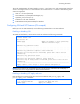
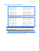
Table 7 Ethernet switch port names
Port number Port alias
13 Downlink13
14 Downlink14
15 Downlink15
16 Downlink16
17 XConnect1
18 Mgmt
19 Uplink1
20 Uplink2
21 Uplink3
22 Uplink4
23 Uplink5
24 Uplink6
25 Uplink7
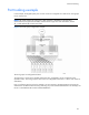
Port trunk groups
When using port trunk groups between two switches, you can create an aggregate link operating at up to
five Gigabits per second, depending on how many physical ports are combined. The switch supports up
to 12 trunk groups per switch, each with up to six ports per trunk group.
The trunking software detects broken trunk links (link down or disabled) and redirects traffic to other trunk
members within that trunk group. You can only use trunking if each link has the same configuration for
speed, flow control, and auto-negotiation.
Statistical load distribution
In a configured trunk group containing more than one port, the load distribution is determined by
information embedded within the data frame. For IP traffic, the switch will calculate the trunk port to
use for forwarding traffic by implementing the load distribution algorithm on value equals to modulus of
(XOR of last 3 bits of Source and last 3 bits of Destination IP address). For non-IP traffic, the switch will
calculate the trunk port to use for forwarding traffic by implementing the load distribution algorithm on
value equals to modulus of (XOR of last 3 bits of Source and last 3 bits of Destination MAC address).
Built-in fault tolerance
Since each trunk group is composed of multiple physical links, the trunk group is inherently fault tolerant.
As long as even one physical link between the switches is available, the trunk remains active.
Statistical load distribution is maintained whenever a link in a trunk group is lost or returned to service.