
HP Virtual Connect 1Gb Ethernet Cookbook


Scenario 2 – Multiple Simple Networks with Active\Active Uplinks Link Aggregation 802.3ad (LACP) - Windows 34
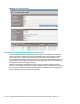
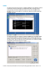
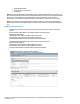
Note: The Port Status and Connected to information. If the connected switch supports LLDP, the
connected to information should be displayed as below.
Figure 27 - Link aggregation confirmed – Bay 1.
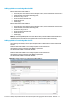
Note: All connections within an active/active LACP group will have the same LAG ID. To view this,
go to the Interconnect bay and view Uplink Port Information. If you are having trouble
establishing an active/active connection, confirm the LAG ID and verify switch configuration for
the ports connecting to each VC module.
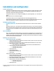
Summary
We created a couple different Virtual Connect Network solutions; based initially for availability
with a higher degree of north/south traffic, both uplinks were active. We later added two
additional links; this increased the network bandwidth to the Virtual Connect network, while still
maintaining availability.
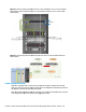
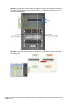
When VC profile App-1 is applied to the server in bay1 and is powered up, it has one NIC through
each virtual connect module, NIC 1 is connected to “vNet-PROD-1”, which connects to the
network infrastructure through a pair of 1Gb uplinks. NIC 2 is connected to vNet-Prod-2, which
connects to the alternate switch through two 1Gb uplinks. These NICs could now be configured as
individual NICs (Figure 28) with their own IP address or as a pair of TEAMED NICs (Figure 29-30).
Either NIC could be active. As a result, this server could access the network through either NIC or
either uplink cable, depending on which is active at the time.
When additional bandwidth was required, additional uplinks were added to the existing vNets,
this process had no effect on the server profile.
As additional servers are added to the enclosure, simply create additional profiles, or copy
existing profiles, configure the NICs for vNet-PROD-1 and vNet-PROD-2 and apply them to the
appropriate server bays.