
HP Virtual Connect for c-Class BladeSystem Version 3.00 Setup and Installation Guide for HP Integrity BL8x0c i2 Series Server Blades

Installation 59
• When multiple external uplink ports are used for the same network, the Virtual Connect Ethernet
modules provide automatic loop prevention by allowing for a single active link or link set at any one
time.
• The Virtual Connect system automatically chooses the uplink (ports) that optimize throughput and
availability. Where possible, links within the uplink port set automatically form a link aggregation
group using LACP. This action requires multiple uplink ports on a single Virtual Connect Ethernet
module to be connected to an external switch that is capable and configured to form link
aggregation groups using LACP.
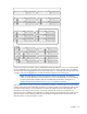
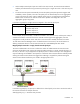
In the following example, a single network is mapped to four external uplink ports.
Network Uplink port set
Production_Network { Enclosure1:Bay1:Port1
Enclosure1:Bay1:Port2
Enclosure1:Bay2:Port1
Enclosure1:Bay2:Port2 }
In this example, the ports from Bay 1 could be connected to one external switch, and the ports on Bay 2
could be connected to a second switch. If the external switches support link aggregation, then this
configuration would provide an active 2-Gb link to one switch and a standby 2-Gb link to the other.
To make Virtual Connect Manager aware of individual network connections, see the information on
defining an Ethernet network in the HP Virtual Connect for c-Class BladeSystem User Guide.
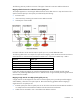
Mapping multiple networks to a single, shared external uplink port
The network administrator can choose to reduce the number of cables between the Virtual Connect
enclosure and the data center switches by mapping multiple networks to a single, shared uplink port. In
this case, a network is not just mapped to an uplink port, but to a VLAN on that port. This configuration
requires VLAN tags to be added to each packet as it leaves the Virtual Connect domain and that packets
entering the Virtual Connect domain be tagged. The VLAN tag is stripped from packets entering the
Virtual Connect domain before they are routed to the appropriate server.
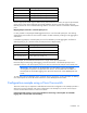
In the following example, an uplink port is defined as a shared uplink port so that it can then be used as
the external connection for multiple networks.
Shared_Uplink_Port_A = Enclosure1:Bay1:PortX2