
HP Virtual Connect Multi-Enclosure Stacking Reference Guide

10
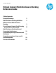
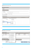
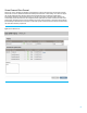
Figure 9: Example of VC FC stacking configuration
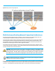
Multi-Enclosure Stacking External Connection Architectures
This section will outline multiple scenarios for stacking 2, 3 and 4 enclosures to form a Multi-Enclosure Stack. Each
example displayed is configured with 4 uplink ports which connect to the external switches.
The Virtual Connect network would be created with an A and B side to allow all links to be in an active state. Blade host
operating systems will need to be configured with NIC teaming to provide both path and module redundancy. More
physical uplinks could be setup and additional Virtual Connect networks defined to reduce latency and provide more
bandwidth to the networking layer, based on needs and application demands.
The following graphics show the physical connections for stacking enclosures that will provide a configuration that is
tolerant of any one module or cable failure. These examples utilize the SFP+ DAC (Direct Attached Copper) connection of
each Flex-10 module to interconnect the enclosures.
Important: The CX-4 and X1 ports on the VC Flex-10 modules are shared. If an SFP/SFP+ or DAC
cable is inserted into X1, the CX-4 port is disabled. CX-4 cables have a distance limitation of 7m for
stacking purposes. SFP+ DAC cables are thinner and more flexible than CX-4 cables, and all SFP+
DAC cables (passive or active) listed in the Quickspecs of the VC module can be used for stacking.
NOTE: CX-4 and SFP+ DAC cables offer a cost effective solution for stacking. Other cabling options supported
by Virtual Connect can still be used and are supported.
It is important to note that the following are only recommended examples. It does not pretend to be an exhaustive list of
all supported stacking configurations. The basic rules for a supported stacking configuration are listed in the “HP Virtual
Connect for c-Class BladeSystem Setup and Installation Guide”. The main rule is that all Virtual Connect Ethernet