0GbE Pass-Thru Module User Guide Part Number 573130-002 December 2010 (Second Edition)
© Copyright 2009, 2010 Hewlett-Packard Development Company, L.P. The information contained herein is subject to change without notice. The only warranties for HP products and services are set forth in the express warranty statements accompanying such products and services. Nothing herein should be construed as constituting an additional warranty. HP shall not be liable for technical or editorial errors or omissions contained herein. Microsoft and Windows are U.S.
Contents Introduction .................................................................................................................................. 5 Features ................................................................................................................................................... 5 Enterprise class performance ............................................................................................................. 5 Configuration and management ............................
Cannot connect to the pass-thru module console interface remotely using Onboard Administrator ...................... 22 The download fails after starting to download the firmware file ..................................................................... 23 The pass-thru module configuration is corrupt .............................................................................................. 23 SFP+ transceiver port is disabled .............................................................................
Introduction Features The 10GbE Pass-Thru Module is designed for easy installation and high performance in an environment where network traffic and users increase continually.
Port mapping For detailed port mapping information, see the HP BladeSystem Enclosure Quick Setup Guide or the HP BladeSystem Enclosure Setup and Installation Guide on the HP website (http://www.hp.com/go/bladesystem/documentation). Dual pass-thru modules In a dual pass-thru module configuration, two pass-thru modules in the HP BladeSystem c7000 Enclosure provide redundant paths to the network ports on the server blades.
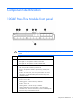
Component identification 10GbE Pass-Thru Module front panel CAUTION: If you press the Reset button while the Health LED is green, the pass-thru module resets. Item Description 1 UID LED • • 2 3 Blue light on—The pass-thru module is activated. Blue light off—The pass-thru module is deactivated. Health LED • • Off—The pass-thru module is powered off. • Amber—An issue exists, such as a port mismatch. For more information, see the HP BladeSystem Enclosure Setup and Installation Guide.
Item Description 4 Reset button 5 Mini-USB RS232 management serial port 6 Ports 1-16 SFP+ ports to support SFP and SFP+ transceiver modules and Direct Attach Cables (DAC).
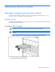
Installing the pass-thru module Manually configuring the pass-thru module Configure the pass-thru module manually using a CLI. See "Accessing the pass-thru module ("Accessing the pass-thru module CLI" on page 10)" for more information. Module security The 10GbE Pass-Thru Module does not provide network security. You must provide security for the module from somewhere else on the network. Installing the module CAUTION: Do not attach the pass-thru module cables until after configuration.
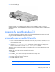
4. Close the handle (2). Complete installation is indicated by a green Health LED. If the Health LED is amber or power is not applied to the module, see the HP BladeSystem Enclosure Setup and Installation Guide for troubleshooting information. Accessing the pass-thru module CLI You can access the pass-thru module CLI remotely using the Onboard Administrator enclosure or locally using the mini-USB to DB-9 RS232 Management serial port. Accessing the pass-thru module CLI remotely 1.
Accessing the pass-thru module CLI locally 1. Using a null-modem mini-USB to DB-9 RS232 serial cable (not included), connect the pass-thru module management port to a local client device (such as a laptop computer). 2.
• The system/info command displays image version, board revision, or chip revisions. • The effect from any CLI command is immediate. For example, configuring auto-negotiation on a port takes effect when the command is completed. • Flow control is not configurable because the pass-thru module cannot handle or generate pause packets. When using the 10GbE Pass-Thru Module, you must ensure that your pause configuration is correct for both link partners.
Replacing a pass-thru module Replacing an existing module CAUTION: Removing the pass-thru module from a powered enclosure results in the loss of network communications between the server blade network ports and the network infrastructure. For continued blade-server network communication and services availability before removing the module, redirect critical high-availability services or applications to use the redundant network ports. CAUTION: Do not connect the pass-thru module until after configuration.
Updating the 10GbE pass-thru firmware Methods for updating the 10GbE Pass-Thru Module firmware CAUTION: The pass-thru module automatically reboots after the firmware update, which disrupts all server traffic on all ports on this pass-thru module. The server blades can be powered on while this pass-thru module firmware is updated, but they lose connectivity while the firmware reboots on each pass-thru module. CAUTION: Do not power off the pass-thru module during the download process.
NOTE: If you are using a USB key to transfer the firmware file, see "Updating the firmware image using a USB key and the Onboard Administrator CLI (on page 17)" for steps that must be completed before beginning this procedure. 1. Access the Onboard Administrator CLI remotely using Telnet or SSH, or locally using a serial connection to the active Onboard Administrator DB9 serial connector, or VGA and keyboard connected to the enclosure KVM ports.
12. Press the Enter key. The module console begins to print C characters until the Xmodem transfer begins. 13. Press Ctrl + Shift + _. The following message appears: Command: D)isconnect, C)hange settings, send B)reak, E)xit command mode X)modem send > 14. Enter x. The following message appears: Xmodem Send: Send a file to the interconnect module using the xmodem transfer protocol. The file can be downloaded to the OA from an HTTP(S), FTP, or TFTP server.
Port 13 is ENABLED Port 14 is ENABLED Port 15 is ENABLED Port 16 is ENABLED Port 1 Installed CU SFP Port 1 Approved CU SFP NOTE: If the module console displays C characters instead of . characters, return to step 14 to restart the Xmodem transfer. 17. Press Ctrl + Shift + _. The following message appears: Command: D)isconnect, C)hange settings, send B)reak, E)xit command mode X)modem send > 18. 19. Enter d.
Secondary DNS: 16.110.135.52 MAC Address: F4:CE:46:86:FA:5D Link Settings: Auto-Negotiation, 100 Mbit, Full Duplex Link Status: Active Enclosure IP Mode: Disabled 8. To begin the firmware upgrade, begin at step 3 of "Updating the firmware image using the Onboard Administrator CLI (on page 14)" and continue following the instructions.
NOTE: The pass-thru module boot code firmware image is usually named 10GPTHRUw.x.y.z_FW.bin, where w.x.y.z is the firmware version number. 1. Using the null modem mini-USB to DB-9 cable, connect the console port of the pass-thru module to the serial port of a computer that supports XModem/1K XModem. 2.
For more information Additional references Configure the 10GbE Pass-Thru Module after installation. Detailed information about how to configure the pass-thru module is available in 10GbE Pass-Thru Module Installation Instructions for HP BladeSystem cClass Enclosures.
Troubleshooting Health LED on the pass-thru module is not on Cause Action The pass-thru module is not seated properly. Be sure that the pass-thru module is inserted completely and seated properly. The enclosure is not powered up. Be sure that the enclosure is powered up and all the power connections are intact. An LED is faulty. Be sure that the pass-thru module is booted. The pass-thru module is faulty. Send the module for repair.
Cannot access the pass-thru module serial console interface using an RS232 connection from a PC Terminal Emulation Program Cause Action The mini-USB to DB-9 RS232 cable is faulty. Try another mini-USB to DB-9 RS232 cable. The connection settings do not match the pass-thru module serial settings. Be sure that the PC Terminal Emulation session settings match the pass-thru module serial settings.
Cause Action More than one person is connected to the module console from Onboard Administrator. Use the Onboard Administrator CLI show interconnect sessions command to check for active sessions. If an interconnect session is active, use the clear interconnect session command to terminate active sessions on the module. The download fails after starting to download the firmware file Cause Action The firmware file is not the correct file or is corrupt.
Technical specifications General specifications Category Specification Auto-negotiation standard: ANSI/IEEE 802.3 Nway Auto-Negotiation Protocols: CSMA/CD Data transfer rates: Gigabit Ethernet Full-Duplex: 2000 Mb/s 10Gb Ethernet Full-Duplex: 20000 Mb/s Connectors: 10GbE Pass-Thru Module 16 SFP+ module connectors 10Gb multimode fiber optic cable 62.
Port Link Ena Speed Neg Approved 12 Up/Downlink Dis/Ena 1Gb/10Gb On/Off Yes/No 13 Up/Downlink Dis/Ena 1Gb/10Gb On/Off Yes/No 14 Up/Downlink Dis/Ena 1Gb/10Gb On/Off Yes/No 15 Up/Downlink Dis/Ena 1Gb/10Gb On/Off Yes/No 16 Up/Downlink Dis/Ena 1Gb/10Gb On/Off Yes/No Physical and environmental specifications Category Specification DC inputs 12 VDC: 6.
From Wire Shell Braid To Shell Technical specifications 26
Regulatory compliance notices Class A equipment This equipment has been tested and found to comply with the limits for a Class A digital device, pursuant to Part 15 of the FCC Rules. These limits are designed to provide reasonable protection against harmful interference when the equipment is operated in a commercial environment.
product family and available (in English only) either within the product documentation or at the following HP website (http://www.hp.eu/certificates) (type the product number in the search field). The compliance is indicated by one of the following conformity markings placed on the product: For non-telecommunications products and for EU harmonized telecommunications products, such as Bluetooth® within power class below 10mW.
WARNING: Use of controls or adjustments or performance of procedures other than those specified herein or in the laser product's installation guide may result in hazardous radiation exposure. To reduce the risk of exposure to hazardous radiation: • Do not try to open the module enclosure. There are no user-serviceable components inside. • Do not operate controls, make adjustments, or perform procedures to the laser device other than those specified herein.
Electrostatic discharge Preventing electrostatic discharge To prevent damaging the system, be aware of the precautions you need to follow when setting up the system or handling parts. A discharge of static electricity from a finger or other conductor may damage system boards or other static-sensitive devices. This type of damage may reduce the life expectancy of the device. To prevent electrostatic damage: • Avoid hand contact by transporting and storing products in static-safe containers.
Acronyms and abbreviations CLI Command Line Interface CPU central processing unit CSMA/CD Carrier Sense Multiple Access with Collision Detection DAC direct attach cable FTP file transfer protocol GMT Greenwich mean time HTTP hypertext transfer protocol HTTPS hypertext transfer protocol secure sockets I/O input/output IEEE Institute of Electrical and Electronics Engineers IP Internet Protocol KVM keyboard, video, and mouse Acronyms and abbreviations 31
LAN local-area network MAC Media Access Control NAS network access server NIC network interface controller OS operating system POST Power-On Self Test SFP small form-factor pluggable SFP+ small form-factor pluggable - plus SSH Secure Shell TFTP Trivial File Transfer Protocol USB universal serial bus VGA video graphics array Acronyms and abbreviations 32
Index A G accessing the pass-thru module CLI 10, 11 accessing the pass-thru module, troubleshooting 22 additional references 20 architecture 5 general specifications 24 grounding methods 30 B Health LED, troubleshooting 21 HyperTerminal, troubleshooting 22 boot code firmware image 14, 17, 18 C Canadian notice 27 CLI (Command Line Interface) 11 CLI menu 11 CLI, commands 11 Command Line Interface (CLI) 11 components, front panel 7 components, identification 7 configuration and management 5, 9 configura
port mapping 6 port names 24 R redundancy 6 regulatory compliance notices 27 replacing an existing pass-thru module 13 replacing the pass-thru module 13 S security 9 self-test, troubleshooting 22 serial console interface, troubleshooting 22 serial download, performing 18 SFP+ transceiver, installing 12 SFP+ transceiver, troubleshooting 23 specifications, environmental 25 specifications, general 24 specifications, physical 25 specifications, technical 24 T technical specifications 24 troubleshooting 21 U