
Medical Archive Solutions User Guide


21
HP Medical Archive
Interface Components
Navigating Locations and Nodes
Once you have logged on to the NMS, the first displayed content is a
Scalable Vector Graphic (SVG) indicating two sites. Icons indicate the
actual installation of Site A and Site B. As you navigate to a site, the
map shows a set of cabinets (the possible maximum of eight); again,
icons above the cabinets indicate the actual installation of your grid. At
the cabinet level, a fully installed cabinet is schematically illustrated
with icons beside the nodes actually installed. For a given node, a sche-
matic image appears with icons for each service installed. Samples are
shown in the following subsections.
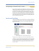
Location and Node Maps
The grid’s geographic locations (the primary site and optional DR site)
are illustrated on the map with a status icon representing actual instal-
lation. The color of the icon gives you an immediate indication of the
location’s alarm state.
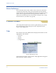
Figure 11: NMS Interface—Sample Grid Map of Locations
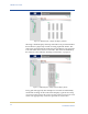
Clicking on an icon displays the next level (the individual location).
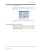
At this level, there are eight cabinets illustrated, the maximum possible
in a single site deployment of the HP Medical Archive. (If a DR site is
used, the maximum at either site is four cabinets, however the illustra-
tion shows the maximum of eight.) Only installed cabinets have an
icon above them.