
Quick Configuration Guide for A7000 dl 1xE1 or 1xE1 + G.703 Modules 2005-04

5991-2117 www.procurve.com 3
1. At the (config)# prompt, enter interface e1 1/1 to activate the interface configuration mode
for the E1 network interface.
2. If necessary (this is the default), enter clock source line
to configure the unit to recover
clocking from the E1 network connection.
The following steps demonstrate configuring an E1 network interface with timeslots 1 through 15
for data.
1. At the (config-e1 1/1)# prompt, enter framing crc4 to enable CRC-4 framing on the
interface.
2. Enter sa4tx-bit 0.
3. Enter tdm-group 1
timeslots 1-15 speed 64 to create a TDM group for timeslots 1 through
15 (the data timeslots) on the E1 network connection (e1 1/1).
4. Enter no shutdown to activate the interface.
5. Enter exit to return to the Global Configuration mode.
Configure the E1 Network Interface
Note
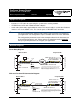
If two routers are configured on a private E1 using PPP (as in the PPP over
fractional E1 diagram), one router must be configured for clock source internal
to provide timing on the circuit and the other to clock source line. Configuring the
routers as such provides a single master clock on the point-to-point circuit and
avoids timing issues. This only applies to circuits that do not contain timing
sources from the provider. Frame relay circuits inherently have a provided clock
source, so all routers connected to the public frame relay network should be set to
clock source line to recover clocking from the network source and avoid timing
issues.
Create the E1 Interface TDM Group
Note
Timeslot 0 is for synchronization, alarm transport, and international carrier use. It
is not accessible for use for voice or data.
Note
Voice circuits require timeslot 16 for signaling. If voice is required on the e1 1/2
G.703 port, the largest data map which can be configured is timeslots 1 through 15
(leaving 17 through 31 for voice) or 17 through 31 (leaving 1 through 15 for voice).
Note
The ProCurve Secure Router automatically maps timeslots 1 through 31 from the
network connection of the E1/FE1 + G.703 interface module to the G.703 port.
Creating a TDM group removes the specified timeslots from the G.703 map. All
remaining timeslots not included in the TDM group will be passed from the
network port (e1 1/1) to the G.703 port (e1 1/2).