installation guide hp procurve switch xl modules www.hp.
HP ProCurve Switch xl Modules Installation Guide
© Copyright 2004 Hewlett-Packard Development Company, L.P. The information contained herein is subject to change without notice. This document contains proprietary information, which is protected by copyright. No part of this document may be photocopied, reproduced, or translated into another language without the prior written consent of Hewlett-Packard.
Contents HP ProCurve Switch xl Modules i Descriptions . . . . . . . . . . . . . . . . . . . . . . . . . . . . . . . . . . . . . . . . . . . . . . . . . . . . 1-1 Features . . . . . . . . . . . . . . . . . . . . . . . . . . . . . . . . . . . . . . . . . . . . . . . . . . . . . . . 1-3 Installing the Modules . . . . . . . . . . . . . . . . . . . . . . . . . . . . . . . . . . . . . . . . . . . 1-5 Overview . . . . . . . . . . . . . . . . . . . . . . . . . . . . . . . . . . . . . . . . . . . . . . . . . . .
Specifications . . . . . . . . . . . . . . . . . . . . . . . . . . . . . . . . . . . . . . . . . . . . . . . . . . 1-28 Environmental . . . . . . . . . . . . . . . . . . . . . . . . . . . . . . . . . . . . . . . . . . . . . 1-28 Lasers . . . . . . . . . . . . . . . . . . . . . . . . . . . . . . . . . . . . . . . . . . . . . . . . . . . . . 1-28 Connectors . . . . . . . . . . . . . . . . . . . . . . . . . . . . . . . . . . . . . . . . . . . . . . . . . 1-29 Twisted-Pair . . . . . . . . . . . . . . . . . . .
HP ProCurve Switch xl Modules Descriptions HP ProCurve Switch xl Modules For the HP ProCurve Series 5300xl Switches Descriptions. The HP ProCurve Switch xl Modules are components that you can add to an HP ProCurve xl switch to provide a variety of network connectivity options.
HP ProCurve Switch xl Modules Descriptions Module HP ProCurve Switch 10/100/1000-T xl Module (J4907A)††† Description 14 twisted-pair ports with RJ-45 connectors for 10/100/1000 Mbps (Gigabit) or 100 Mbps operation over Category 5 or better 100-ohm UTP or STP cable (category 5e recommended for Gigabit) -- all ports have the IEEE 802.3ab Auto MDI/MDI-X feature, and 2 slots for installing any of the supported HP ProCurve mini-GBICs*.
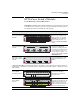
HP ProCurve Switch xl Modules Features Features Link and Mode LEDs (one pair per port) retaining screw hp procurve 10/100-TX xl module xl module J4820A network ports Example: The HP ProCurve 24-Port 10/100-TX xl Module LED Mode Select Button PoE Link EPS Status LED Mode EPS Input Std PoE-Ready 10/100-TX Ports (1-24) all ports are HP Auto-MDIX PoE 1 Mode 2 3 4 5 7 8 9 10 11 6 13 14 15 16 17 20 21 22 23 Link 18 Mode PoE hp procurve PoE xl module J8161A xl Link and Mo
HP ProCurve Switch xl Modules Features The HP ProCurve Switch xl Modules have the following features: 4 ■ auto-enabled ports—the ports are all configured to be ready for network operation as soon as a viable network cable is connected ■ auto-configuration—a default configuration is applied to the module when the switch is powered on and the module passes self test; this default configuration works well for most network installations ■ LEDs that provide information for each port on the link status, n
HP ProCurve Switch xl Modules Installing the Modules Installing the Modules Overview You can install any of the modules into any of the HP ProCurve xl Switches that have a compatible module slot. As of this printing, those are the HP ProCurve Series 5300xl Switches: ■ 5308xl (p/n J4819A) ■ 5372xl (p/n J4848B) ■ 5348xl (p/n J4849B) ■ 5304xl (p/n J4850A) “Hot Swap” Notes The mini-GBICs can be “hot swapped”.
HP ProCurve Switch xl Modules Installing the Modules Installing the Module in an Unused Slot Installation Precautions: ■ Static electricity can severely damage the electronic components on the modules. When handling and installing the modules in your switch, follow these procedures to avoid damage from static electricity: • Handle the module by its bulkhead or edges and avoid touching the components and the circuitry on the board.
HP ProCurve Switch xl Modules Installing the Modules 1. Insert module into the guides and slide it in until it is fully inserted. “Low-force” connector. High insertion force is not needed and should not be used. For best results, push simultaneously near both screws. The module is fully inserted when the module bulkhead is contacting, or very close to contacting the face of the switch. 2. Then tighten the retaining screws on the module until they are secure, but do not overtighten them.
HP ProCurve Switch xl Modules Installing the Modules Installing or Removing the mini-GBICs You can install or remove a mini-GBIC from the mini-GBIC xl Module without having to power off the switch. Use only HP ProCurve mini-GBICs. WA R N I N G The HP ProCurve mini-GBICs are Class 1 laser devices. Avoid direct eye exposure to the beam coming from the transmit port.
HP ProCurve Switch xl Modules Installing the Modules Connecting an HP ProCurve 600 Redundant and External Power Supply Power over Ethernet technology allows IP telephones, wireless LAN Access Points and other appliances to receive power as well as data over existing LAN cabling, without needing to modify the existing Ethernet infrastructure. For more information on PoE, refer to the HP ProCurve PoE Planning and Implementation Guide.
HP ProCurve Switch xl Modules Installing the Modules 4. Secure the CRB to the module bulkhead. 5. Install (or re-install) the RJ45 connectors in ports 6 and 13. The opposite procedure is used when disconnecting the EPS cable connector. Connecting or disconnecting RJ-45 connectors To insert or remove an RJ-45 connector in port 6 or 13, depress the RJ-45 connector clip in order to clear the EPS cable retention bracket.
HP ProCurve Switch xl Modules Installing the Modules HP ProCurve Switch PoE xl Module Configurations For the HP ProCurve Switch PoE xl Module to function it must be installed in any slot of an HP ProCurve Switch 5300xl. The module will receive it’s operational power from the switch and it’s PoE power from the HP 600 RPS/EPS. The following examples show the two possible configurations.
HP ProCurve Switch xl Modules Installing the Modules PoE Power Requirements # of Modules being Powered Watts Available # of Ports Powered and Average Watts/Port One Module 408 24 @ average 15.4 W each Two Modules 204/each module 24 @ average 7.6 W each When a powered device (PD) is initially connected to a PoE port, a minimum of 15.4 watts of available power is required to begin the power-up sequence. This 15.4 watts is needed to determine the type of PD requesting power.
HP ProCurve Switch xl Modules Installing the Modules . Chassis Mode Switch Description Setting Port Indication - LED On Act Activity Transmit or Receive Traffic Present FDx Full Duplex Full Duplex Mode of Operation Max Maximum Speed Operation in 100Mbps ! Attention Experiencing any of a fixed set of errors If the module’s LED mode is PoE, the Mode LED provides information on the status of the PoE connection for that port: ■ If the Mode LED in on the port is providing PoE power.
HP ProCurve Switch xl Modules Installing the Modules Verifying the Module is Installed Correctly Observe the Module Status LED for the slot in which the module is being installed, and the Self Test and Fault LEDs on the switch to verify the module is installed properly.
HP ProCurve Switch xl Modules Installing the Modules Connecting the Network Cables Connect the appropriate network cables to the module's ports as shown in the table below. For more information on the cable specifications, see “Cables” on page 30.
HP ProCurve Switch xl Modules Installing the Modules Module mini-GBIC and the 10/100/1000-T xl Modules Link hp procurve 1 2 1 3 4 3 2 4 xl mini-GBIC xl module J4878A Cable Type Maximum Length Gigabit-SX operation: multimode fiber-optic cables fitted with LC connectors 220 meters to 550 meters, depending on the cable used. See “Fiber-Optic Cables” on page 31 for more information. Gigabit-LX operation: single-mode fiberoptic cables fitted with LC connectors.
HP ProCurve Switch xl Modules Installing the Modules Note Automatic Cable Sensing on Twisted-Pair Ports: When the ports for the 10/100-TX, 100/1000-T, 10/100/1000-T, and the PoE xl Modules are in their default configuration, Auto, they automatically negotiate whether the ports operate as MDI or MDI-X, depending on the cable type and the connected device’s operation. As a result, you can use either straight-through or crossover twisted-pair cable for all network connections to these modules.
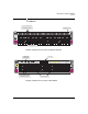
HP ProCurve Switch xl Modules Installing the Modules Verifying the Network Connections Are Working Check the port LEDs for the newly-installed module to ensure the port(s) connected in the preceding step are operating correctly. Each port on the switch modules has Link and Mode LEDs near it as shown in the next illustration.
HP ProCurve Switch xl Modules Installing the Modules Customizing the Port Configuration If the slot in which you installed the module was empty the last time the switch was either rebooted or reset (or the power to the switch was cycled), then the module will use preconfigured default parameter values that will work for most networks.
HP ProCurve Switch xl Modules Installing the Modules Note 20 By default, all ports on the PoE xl module have PoE power enabled. For information regarding customizing PoE ports refer to “Power over Ethernet (PoE) Operation” in the Management and Configuration Guide and the HP ProCurve PoE Planning and Implementation Guide.
HP ProCurve Switch xl Modules Replacing or Removing a Module Replacing or Removing a Module Follow these procedures to replace one module with another, or to remove a module without replacing it: 1. Remove any network cables from the ports on the module. (If this is a PoE xl Module, also remove the PoE cable.) 2. On the module you want to remove from the switch, unscrew the retaining screws enough to disconnect them from the threaded holes in the switch.
HP ProCurve Switch xl Modules Resetting the Switch Resetting the Switch Reasons for Resetting the Switch Generally, you only need to reset the switch when it needs to recognize a change in its hardware or software (console) configuration.
HP ProCurve Switch xl Modules Troubleshooting Troubleshooting One of the primary tools for troubleshooting the switch modules are the LEDs on the front of the switch and on the modules. Refer to “LED Behavior” on page 14 for a description of the normal LED behavior. Also, refer to the switch Installation and Getting Started Guide for more detailed troubleshooting information for the switch. PoE LED Behavior EPS EPS Status EPS Condition Fault LED EPS Device Conn.
HP ProCurve Switch xl Modules Troubleshooting * On - When power is being supplied to the ports Off - When power is not requested Slow Blink - When power is requested, but not supplied Switch and Module LED Error Indicators: † †† Fault Self Test Module Status Port Link Diagnostic Tips Flashing† Flashing† Flashing† Never On ➊ Flashing† Flashing† Flashing† On briefly, then Off ➋ Off Off Flashing† Off ➌ Flashing† Flashing† Flashing† Flashing† ➍ Off Off Off Fast Flashing†† ➎ Off
HP ProCurve Switch xl Modules Troubleshooting Tip Numbe r ➋ Problem Solution The module installed in the slot that corresponds to the letter that is flashing has experienced a self test or initialization fault. The modules are all tested whenever the switch is powered on, or reset (through the Reset button on the switch, or the Reboot or Reset options in the console or web browser interface), and when they are hot swapped (installed when the switch is powered on).
HP ProCurve Switch xl Modules Troubleshooting Tip Numbe r ➍ Problem Solution The network port for which the Link LED is flashing has experienced a self test or initialization failure. During the module self test (described in item 1 above), each network port is also tested. If the port self test fails, the individual port is not usable, but the rest of the ports on the module, which have passed their self test, will continue to operate normally.
HP ProCurve Switch xl Modules Troubleshooting Tip Numbe r ➏ Problem The network connection is not working properly. Solution Try the following procedures: • For the indicated port, verify both ends of the cabling, at the switch and the connected device, are securely connected. • Verify the connected device and switch are both powered on and operating correctly. • Verify you have used the correct cable type for the connection. See “Cables” on page 30 for the correct cable specifications.
HP ProCurve Switch xl Modules Customer Support Services Customer Support Services If you are having any trouble with your module or switch, Hewlett-Packard offers support 24 hours a day, seven days a week through the use of a number of automated electronic services. See the Customer Support/Warranty booklet that came with your switch for information on how to use these services to get technical support. The HP networking products World Wide Web site, http://www.hp.
HP ProCurve Switch xl Modules Specifications Connectors Twisted-Pair ■ 10/100Base-TX RJ-45 – On the 10/100-TX xl Module. They are compatible with the IEEE 802.3 10Base-T and 802.3u 100Base-TX standards and accepts the 10 Mbps or 100 Mbps cables listed on the next page. ■ 100/1000Base-T RJ-45 – On the 100/1000-T and the 10/100/1000-T xl Modules. They are compatible with the IEEE 802.3u 100Base-TX and IEEE 802.3ab 1000Base-T standards, and accepts the 100 Mbps or 1000 Mbps cables listed on the next page.
HP ProCurve Switch xl Modules Specifications Cables Twisted-Pair Cables Port Type Cable Specifications Maximum Length 10 Mbps Operation Category 3, 4, or 5 100-ohm balanced unshielded twisted-pair (UTP) or shielded twisted-pair (STP) cable, complying with IEEE 802.3 10Base-T specifications, fitted with RJ-45 connectors 100 meters 100 Mbps Operation Category 5 100-ohm balanced UTP or STP cable, complying with IEEE 802.
HP ProCurve Switch xl Modules Specifications Fiber-Optic Cables Port Type Cable Specifications Connecto r Type Maximum Length 100Base-FX 62.5/125 µm or 50/125 µm (core/cladding) diameter, graded-index, low metal content, multimode fiber-optic cables, complying with the ITU-T G.651 and ISO/IEC 793-2 Type A1b or A1a respectively. MT-RJ • full-duplex connections: 2 kilometers • half-duplex connections: 412 meters Gigabit-SX 62.
HP ProCurve Switch xl Modules Mode Conditioning Patch Cord for Gigabit-LX Mode Conditioning Patch Cord for GigabitLX The following information applies to installations in which multimode fiber-optic cables are connected to a Gigabit-LX port. Unlike Gigabit-SX, which connects to only multimode fiber-optic cabling, GigabitLX can use either single-mode or multimode cable.
HP ProCurve Switch xl Modules Mode Conditioning Patch Cord for Gigabit-LX Installing the Patch Cord As shown in the illustration below, connect the patch cord to the Gigabit-LX miniGBIC with the section of single-mode fiber plugged in to the Tx (transmit) port. Then, connect the other end of the patch cord to your network cabling patch panel, or directly to the network multimode fiber.
HP ProCurve Switch xl Modules EMC Regulatory Statements EMC Regulatory Statements U.S.A. FCC Class A This equipment has been tested and found to comply with the limits for a Class A digital device, pursuant to Part 15 of the FCC Rules. These limits are designed to provide reasonable protection against interference when the equipment is operated in a commercial environment.
HP ProCurve Switch xl Modules EMC Regulatory Statements Korea Taiwan European Community Declaration of Conformity These products are designed for operation with the HP ProCurve switches that have xl module slots. Please see the Declarations of Conformity included in the Installation Guides for those products.
— This page is intentionally unused.
— This page is intentionally unused.
Technical information in this document is subject to change without notice. Copyright Hewlett-Packard Company, 2004. All rights reserved. Reproduction, adaptation, or translation without prior written permission is prohibited except as allowed under the copyright laws.