Installation Guide ProCurve Switch vl Modules PoE Power over Ethernet Devices www.hp.
ProCurve Switch vl Modules Installation Guide
© Copyright 2005 -2007, 2012 Hewlett-Packard Development Company, L.P. Disclaimer HEWLETT-PACKARD COMPANY MAKES NO WARRANTY OF ANY KIND WITH REGARD TO THIS MATERIAL, INCLUDING, BUT NOT LIMITED TO, THE IMPLIED WARRANTIES OF MERCHANTABILITY AND FITNESS FOR A PARTICULAR PURPOSE. Hewlett-Packard shall not be liable for errors contained herein or for incidental or consequential damages in connection with the furnishing, performance, or use of this material.
Contents ProCurve Switch vl Modules Descriptions . . . . . . . . . . . . . . . . . . . . . . . . . . . . . . . . . . . . . . . . . . . . . . . . . . . . 1 Features . . . . . . . . . . . . . . . . . . . . . . . . . . . . . . . . . . . . . . . . . . . . . . . . . . . . . . . . 3 The ProCurve Switch vl Modules have the following features: . . . 4 Installing the Modules . . . . . . . . . . . . . . . . . . . . . . . . . . . . . . . . . . . . . . . . . . . . 5 Overview . . . . . . . . . . . . . . . . . . . . . .
Cables . . . . . . . . . . . . . . . . . . . . . . . . . . . . . . . . . . . . . . . . . . . . . . . . . . . . . Twisted-Pair Cables . . . . . . . . . . . . . . . . . . . . . . . . . . . . . . . . . . . . . . Fiber-Optic Cables . . . . . . . . . . . . . . . . . . . . . . . . . . . . . . . . . . . . . . . Fiber-Optic Cables . . . . . . . . . . . . . . . . . . . . . . . . . . . . . . . . . . . . . . . Copper 10-GbE Cables . . . . . . . . . . . . . . . . . . . . . . . . . . . . . . . . . . .
ProCurve Switch vl Modules Descriptions ProCurve Switch vl Modules For the ProCurve Series 4200vl Switches Descriptions. The ProCurve Switch vl Modules are components that you can add to a ProCurve vl switch to provide a variety of network connectivity options. The following ProCurve vl switches are available as of this printing: ■ ProCurve Switch 4204vl (J8770A), a chassis with four open slots. ■ ProCurve Switch 4208vl (J8773A), a chassis with eight open slots.
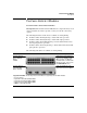
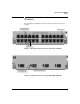
ProCurve Switch vl Modules Descriptions Module ProCurve Switch vl 12-Port 100-FX MTRJ Module (J8763A) Description Link|Mode 1 3 2 5 4 6 7 8 9 10 12 11 100Base-FX MTRJ Ports 1 2 3 4 5 6 7 8 9 10 11 12 ProCurve vl 100-FX MTRJ vl Module Module J8763A ProCurve Switch vl 16Port Gig-T Module (J8764A) 10/100/1000Base-T Ports all ports are HP Auto MDI-X 1 3 5 7 9 11 13 15 2 4 6 8 10 12 14 16 ProCurve 16p Gig-T vl Module vl J8764A ProCurve Switch vl 24-Port Gig-
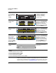
ProCurve Switch vl Modules Features Features The following two illustrations show the features found on the various modules. Link and Mode LEDs (one pair per port) retaining screw network ports Figure 1. Example: ProCurve 24-Port 10/100-TX vl Module Link and Mode LEDs (one pair per port) Mini-GBIC and SFP ports Figure 2.
ProCurve Switch vl Modules Features Link and Mode LEDs port covers Figure 3.
ProCurve Switch vl Modules Installing the Modules ■ the ports on the 10/100-TX vl Module have the HP Auto MDI-X feature, and the ports on the Gig-T vl Module have the IEEE 802.3ab Auto MDI/ MDI-X feature. These features operate the same way and allow you to use either straight-through or crossover twisted-pair cables for all the twisted-pair network connections. Please see the note on “Automatic Cable Sensing” on page 13. ■ standards adherence: • the 10/100-TX vl Module is compatible with the IEEE 802.
ProCurve Switch vl Modules Installing the Modules Note Note The mini-GBICs can be “hot swapped”. That is, they can be installed or removed after the mini-GBIC vl Module, or the Gig-T/SFP vl Module, is installed in the switch and the module is receiving power. The network cable must be removed from the mini-GBIC before installing or removing a miniGBIC. For more information, see page 9. 3. Verify the modules are installed correctly (see page 12). 4. Connect the network cabling (see page 13). 5.
ProCurve Switch vl Modules Installing the Modules Installing the Module in an Unused Slot Installation Precautions: ■ Static electricity can severely damage the electronic components on the modules. When handling and installing the modules in your switch, follow these procedures to avoid damage from static electricity: • Handle the module by its bulkhead or edges and avoid touching the components and the circuitry on the board.
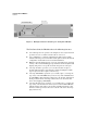
ProCurve Switch vl Modules Installing the Modules Insert module into the guides and slide it in until it is fully inserted. “Low-force” connector. High insertion force is not needed and should not be used. For best results, push simultaneously near both screws. Figure 4.
ProCurve Switch vl Modules Installing the Modules The module is fully inserted when the module bulkhead is contacting, or very close to contacting the face of the switch. Then tighten the retaining screws on the module until they are secure, but do not overtighten them. Figure 5. Tighten module retaining screws Installing or Removing the Mini-GBICs Note Hot swapping mini-GBICs is supported. You can install or remove a mini-GBIC with the switch powered on, a reset will not occur.
ProCurve Switch vl Modules Installing the Modules Caution Use only supported genuine ProCurve mini-GBICs with your switch. NonProCurve mini-GBICs are not supported, and their use may result in product malfunction. Should you require additional ProCurve mini-GBICs, contact your ProCurve Networking Sales and Service Office or authorized dealer. Installing the mini-GBICs: Hold the mini-GBIC by its sides and gently insert it into any of the slots in the module until the mini-GBIC clicks into place. Figure 6.
ProCurve Switch vl Modules Installing the Modules Install or Remove a Transceiver Note Hot swapping transceivers is supported. You can install or remove a transceiver with the switch powered on, a reset will not occur. a. Slide the transceiver in until it stops. Figure 7. Installing an X2 transceiver b. Push firmly until the gasket seats against the bulkhead. The transceiver should “click” into place. Figure 8.
ProCurve Switch vl Modules Installing the Modules Verifying the Module is Installed Correctly Observe the Module Status LED for the slot in which the module is being installed, and the Self Test and Fault LEDs on the switch to verify the module is installed properly.
ProCurve Switch vl Modules Installing the Modules Connecting the Network Cables Note Automatic Cable Sensing on Twisted-Pair Ports: When the ports for the 10/100-TX and the Gig-T vl Modules are in their default configuration, Auto, both modules automatically negotiate whether the ports operate as MDI or MDI-X, depending on the cable type and the connected device’s operation. As a result, you can use either straight-through or crossover twisted-pair cables for all network connections to these modules.
ProCurve Switch vl Modules Installing the Modules Connect the appropriate network cables to the module's ports as shown in the table below. For more information on the cable specifications, see “Cables” on page 28.
ProCurve Switch vl Modules Installing the Modules Module Mini-GBIC vl Module Installed mini-GBIC ! Use only ProCur ve Mini-GBICs and SFPs 1 2 3 Cable Type Maximum Length Gigabit-SX operation: multimode fiber-optic cables fitted with LC connectors 220 meters to 550 meters, depending on the cable used. See “Fiber-Optic Cables” on page 29 for more information. Gigabit-LX operation: single-mode fiberoptic cables fitted with LC connectors.
ProCurve Switch vl Modules Installing the Modules Connecting the 10-GbE Network cables Connecting a fiber cable. 1. Remove the dust covers from the cable connectors and the port. 2. Aligning the notches on the cable connectors with the slots of the port, press the cable connector into the port until it snaps into place. If the Link LED does not go on when the network cable is connected to the port, see “LED Error Indicators:” on page 21, in chapter 5, “Troubleshooting”. 2 Figure 10.
ProCurve Switch vl Modules Installing the Modules Verifying the Network Connections Are Working Check the port LEDs for the newly-installed module to ensure that the port(s) connected in the preceding step are operating correctly. Each port on the switch modules has Link and Mode LEDs near it as shown in the next illustration. Link and Mode LEDs Figure 12. Checking Link and Mode LEDs ■ The Link LED will be lit for each port that is connected properly to an active network device.
ProCurve Switch vl Modules Installing the Modules Default Port Configuration If the slot in which you installed the module was empty the last time the switch was either rebooted or reset (or the power to the switch was cycled), then the module will use preconfigured default parameter values that will work for most networks.
ProCurve Switch vl Modules Replacing or Removing a Module Replacing or Removing a Module Follow these procedures to replace one module with another, or to remove a module without replacing it: 1. Remove any network cables from the ports on the module to be removed. 2. Unscrew the retaining screws enough to disconnect them from the threaded holes in the switch. unscrew the retaining screws Figure 13. Retaining screws Caution 3. Grab the screws and pull the module out from the slot.
ProCurve Switch vl Modules Resetting the Switch Resetting the Switch Reasons for Resetting the Switch Generally, you only need to reset the switch when it needs to recognize a change in its hardware or software (console) configuration.
ProCurve Switch vl Modules Troubleshooting Troubleshooting One of the primary tools for troubleshooting the switch modules is the LEDs on the front of the switch and on the modules. Refer to “LED Behavior” on page 12 for a description of the normal LED behavior. Also, refer to the switch Installation and Getting Started Guide for more detailed troubleshooting information for the switch.
ProCurve Switch vl Modules Troubleshooting 1 1 1 Fast Flashing3 L Port security disabled the port On Off Off 1 1 1 Off with cable connected M No link on port 1 Fault Port Link Module Status (one LED per module) Off Fan Status Off Self Test On Power Power Status (one LED per power supply) LED Pattern Indicating Problems Diag Tips Brief Problem Description This LED is not important for the diagnosis. 2 The flashing behavior is an on/off cycle once every 1.
ProCurve Switch vl Modules Troubleshooting Tip Letter Problem Solution C One or more of the switch cooling fans may have failed. Try disconnecting power from the switch and wait a few moments. Then reconnect the power to the switch and check the LEDs again. If the error indication reoccurs, one or more of the fans have failed.
ProCurve Switch vl Modules Troubleshooting Tip Letter 24 Problem Solution G The module installed in the slot that corresponds to the letter that is flashing has experienced a self test or initialization fault. The modules are all tested whenever the switch is powered on, or reset (through the Reset button on the switch, or the Reboot or Reset options in the console or web browser interface), and when they are hot swapped (installed when the switch is powered on).
ProCurve Switch vl Modules Troubleshooting Tip Letter Problem Solution J The mini-GBIC or SFP installed in the mini-GBIC slot for which the Link LED is flashing is an invalid or unsupported transceiver. Ensure you have installed a model B or greater ProCurve mini-GBIC or SFP in the slot. Model A mini-GBICs are not supported in the Series 4200vl Switches.
ProCurve Switch vl Modules Troubleshooting Tip Letter M Problem The network connection is not working properly. Solution Try the following procedures: • For the indicated port, verify both ends of the cabling, at the switch and the connected device, are securely connected. • Verify the connected device and switch are both powered on and operating correctly. • Verify you have used the correct cable type for the connection.
ProCurve Switch vl Modules Customer Support Services Customer Support Services If you are having any trouble with your module or switch, Hewlett-Packard offers support 24 hours a day, seven days a week through the use of a number of automated electronic services. See the Customer Support/Warranty booklet that came with your switch for information on how to use these services to get technical support. The ProCurve networking products Web site, www.procurve.com also provides up-to-date support information.
ProCurve Switch vl Modules Specifications Cables Twisted-Pair Cables Port Type Cable Specifications Maximum Length 10 Mbps Operation Category 3, 4, or 5 100-ohm balanced unshielded twisted-pair (UTP) or shielded twisted-pair (STP) cable, complying with IEEE 802.3 10Base-T specifications, fitted with RJ-45 connectors 100 meters 100 Mbps Operation Category 5 100-ohm balanced UTP or STP cable, complying with IEEE 802.
ProCurve Switch vl Modules Specifications Fiber-Optic Cables Port Type 100Base-FX Cable Specifications Connector Type 62.5/125 μm or 50/125 μm (core/cladding) MT-RJ or diameter, graded-index, low metal content, LC multimode fiber-optic cables, complying with the ITU-T G.651 and ISO/IEC 793-2 Type A1b or A1a respectively. Maximum Length • full-duplex connections: 2 kilometers • half-duplex connections: 412 meters Note: MT-RJ connector is on the module or an LC connector on the SFP transceiver.
ProCurve Switch vl Modules Specifications Fiber-Optic Cables Port Type Cable Specifications Connector Type Supported Length 10-GbE SR Multimode fiber-optic cable designed for Gigabit Ethernet: 62.5/125 μm (core/cladding) diameter or 50/125 μm, low metal content, complying with the ITU-T G.652 and ISO/IEC 7932 Type B1 standards. SC 10-GbE LR 9/125 μm (core/cladding) diameter, low metal content, single mode fiber-optic cables, complying with the ITU-T G.652 and ISO/IEC 7932 Type B1 standards.
ProCurve Switch vl Modules Specifications Optical Specifications ProCurve 10-GbE X2-SC SR optic Transmitter Optical Characteristics: Parameter Center Wavelength Minimum Typical Maximum 840nm 850nm 860nm Spectral Width Notes 0.45 nm Average Launch Power -7.3 dBm Extinction Ratio 3 dB -1.0 dBm RIN (Relative Intensity Noise) -128 dB/Hz Receiver Optical Characteristics: Parameter Center Wavelength Average Receive Power Minimum Typical Maximum 840nm 850nm 860nm -9.9 dBm Notes -1.
ProCurve Switch vl Modules Specifications Receiver Optical Characteristics: Parameter Center Wavelength Average Receive Power Minimum Typical Maximum 1260 nm 1310 nm 1355 nm - 14.4 dBm Notes 0.5 dBm Receiver Sensitivity -12.6 dBm ProCurve 10-GbE X2-SC ER optic Transmitter Optical Characteristics: Parameter Minimum Typical Maximum Center Wavelength 1530 nm 1550 nm 1565 nm Average Launch Power -4.7 dBm Extinction Ratio 3.0 dB Notes 4.
ProCurve Switch vl Modules Specifications ProCurve 10-GbE X2-CX4 Transceiver Copper Transceiver Characteristics: Parameter Minimum Typical Maximum OMC Supply Voltage 3.3V* 3.13 VDC 3.3 VDC 4.37 VDC 196 mA 216 mA OMC Supply Current 3.
ProCurve Switch vl Modules Mode Conditioning Patch Cord for Gigabit-LX Mode Conditioning Patch Cord for Gigabit-LX The following information applies to installations in which multimode fiberoptic cables are connected to a Gigabit-LX port. Unlike Gigabit-SX, which connects to only multimode fiber-optic cabling, Gigabit-LX can use either single-mode or multimode cable.
ProCurve Switch vl Modules Mode Conditioning Patch Cord for Gigabit-LX Installing the Patch Cord As shown in the illustration below, connect the patch cord to the Gigabit-LX mini-GBIC with the section of single-mode fiber plugged in to the Tx (transmit) port. Then, connect the other end of the patch cord to your network cabling patch panel, or directly to the network multimode fiber.
ProCurve Switch vl Modules EMC Regulatory Statements EMC Regulatory Statements U.S.A. FCC Class A This equipment has been tested and found to comply with the limits for a Class A digital device, pursuant to Part 15 of the FCC Rules. These limits are designed to provide reasonable protection against interference when the equipment is operated in a commercial environment.
ProCurve Switch vl Modules EMC Regulatory Statements Korea Taiwan 37
ProCurve Switch vl Modules Waste Electrical and Electronic Equipment (WEEE) Statements Waste Electrical and Electronic Equipment (WEEE) Statements Disposal of Waste Equipment by Users in Private Household in the European Union This symbol on the product or on its packaging indicates that this product must not be disposed of with your other household waste.
ProCurve Switch vl Modules Waste Electrical and Electronic Equipment (WEEE) Statements Laitteiden hävittäminen kotitalouksissa Euroopan unionin alueella Jos tuotteessa tai sen pakkauksessa on tämä merkki, tuotetta ei saa hävittää kotitalousjätteiden mukana. Tällöin hävitettävä laite on toimitettava sähkölaitteiden ja elektronisten laitteiden kierrätyspisteeseen.
ProCurve Switch vl Modules Waste Electrical and Electronic Equipment (WEEE) Statements Smaltimento delle apparecchiature da parte di privati nel territorio dell'Unione Europea Questo simbolo presente sul prodotto o sulla sua confezione indica che il prodotto non può essere smaltito insieme ai rifiuti domestici. È responsabilità dell'utente smaltire le apparecchiature consegnandole presso un punto di raccolta designato al riciclo e allo smaltimento di apparecchiature elettriche ed elettroniche.
ProCurve Switch vl Modules Waste Electrical and Electronic Equipment (WEEE) Statements Descarte de Lixo Elétrico na Comunidade Européia Este símbolo encontrado no produto ou na embalagem indica que o produto não deve ser descartado no lixo doméstico comum. É responsabilidade do cliente descartar o material usado (lixo elétrico), encaminhando-o para um ponto de coleta para reciclagem.
© Copyright 2005 - 2007, 2012 Hewlett-Packard Company, L.P.