HP High Performance Clusters LC 2000 Series Cabling Guide March 2004 (First Edition) Part Number 365685-001
© Copyright 2004 Hewlett-Packard Development Company, L.P. The information contained herein is subject to change without notice. The only warranties for HP products and services are set forth in the express warranty statements accompanying such products and services. Nothing herein should be construed as constituting an additional warranty. HP shall not be liable for technical or editorial errors or omissions contained herein.
Contents About This Guide Audience Assumptions..................................................................................................................................v Where to Go for Additional Help..................................................................................................................v Technical Support ...................................................................................................................................
Contents Chapter 7 24 Node Fast Ethernet Expandable to 36 Nodes Rack Diagram ............................................................................................................................................7-2 Point-to-Point Cabling Guide ....................................................................................................................7-3 Chapter 8 32 Node Myrinet Expandable to 64 Nodes Rack Diagram ..............................................................................
About This Guide This guide provides cabling information for the HP High Performance Cluster LC 2000. Audience Assumptions This guide is for the person who installs, administers, and troubleshoots servers. HP assumes you are qualified in the servicing of computer equipment and trained in recognizing hazards in products with hazardous energy levels and are familiar with weight and stability precautions for rack installations.
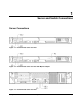
1 Server and Switch Connections Server Connections Figure 1-1: ProLiant DL360 server rear view Figure 1-2: ProLiant DL360 server rear view with Myrinet adapter Figure 1-3: ProLiant DL380 server rear view HP High Performance Clusters LC 2000 Series Cabling Guide 1-1
Server and Switch Connections Switch Connections Figure 1-4: ProCurve 2650 rear view Figure 1-5: ProCurve 2848 rear view Figure 1-6: ProCurve 5372 rear view showing all modules 1-2 HP High Performance Clusters LC 2000 Series Cabling Guide
Server and Switch Connections Figure 1-7: Myricom 5 slot switch rear view Figure 1-8: Myricom 9 slot switch rear view HP High Performance Clusters LC 2000 Series Cabling Guide 1-3
Server and Switch Connections Figure 1-9: Myricom 17 slot switch rear view 1-4 HP High Performance Clusters LC 2000 Series Cabling Guide
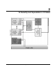
2 16 Node Myrinet Expandable to 32 Nodes HP High Performance Clusters LC 2000 Series Cabling Guide 2-1
16 Node Myrinet Expandable to 32 Nodes Rack Diagram 2-2 HP High Performance Clusters LC 2000 Series Cabling Guide
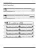
16 Node Myrinet Expandable to 32 Nodes Point-to-Point Cabling Guide Table 2-1: Cable Label Nomenclature Symbol Description R Rack number S Control/Compute/Storage node number SW Out of Band (OOB) Management Switch/Cluster Interconnect Switch/In Band (IB) Management Switch number M Module letter or Module number P Port number NIC NIC port number iLO iLO port PCI Myrinet Adapter (in PCI slot) Table 2-2: 16 Node Myrinet Cabling for DL360 LC Clusters Expandable to 32 Nodes OOB Switch Cabling
16 Node Myrinet Expandable to 32 Nodes Table 2-2: 16 Node Myrinet Cabling for DL360 LC Clusters Expandable to 32 Nodes continued OOB Switch Cabling Origin (server) Cluster Interconnect Switch Cabling Destination (switch) Origin (server) IB Management Switch Cabling Destination (switch) Origin (server) Destination (switch) R1-S14-ILO R1-SW3-P14 R1-S14-PCI R1-SW1-M2-P13 R1-S14-NIC1 R1-SW2-P14 R1-S15-ILO R1-SW3-P15 R1-S15-PCI R1-SW1-M2-P14 R1-S15-NIC1 R1-SW2-P15 R1-S16-ILO R1-SW3-P16 R1-
3 16 Node GigE Expandable to 22 Nodes HP High Performance Clusters LC 2000 Series Cabling Guide 3-1
16 Node GigE Expandable to 22 Nodes Rack Diagram 3-2 HP High Performance Clusters LC 2000 Series Cabling Guide
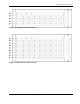
Node GigE Expandable to 22 Nodes Point-to-Point Cabling Guide Table 3-1: Cable Label Nomenclature Symbol Description R Rack number S Control/Compute/Storage node number SW Out of Band (OOB) Management Switch/Cluster Interconnect Switch/In Band (IB) Management Switch number M Module letter or Module number P Port number NIC NIC port number iLO iLO port Table 3-2: 16 Node GigE Cabling for DL360 LC Clusters Expandable to 22 Nodes OOB Switch Cabling Origin (server) Destination (switch) Clu
16 Node GigE Expandable to 22 Nodes Table 3-2: 16 Node GigE Cabling for DL360 LC Clusters Expandable to 22 Nodes continued OOB Switch Cabling Origin (server) Cluster Interconnect Switch Cabling Destination (switch) Origin (server) IB Management Switch Cabling Destination (switch) Origin (server) Destination (switch) R1-S14-ILO R1-SW2-P14 R1-S14-NIC2 R1-SW1-P14 R1-S14-NIC1 R1-SW1-P36 R1-S15-ILO R1-SW2-P15 R1-S15-NIC2 R1-SW1-P15 R1-S15-NIC1 R1-SW1-P37 R1-S16-ILO R1-SW2-P16 R1-S16-NIC2
4 16 Node Fast Ethernet Expandable to 22 Nodes HP High Performance Clusters LC 2000 Series Cabling Guide 4-1
16 Node Fast Ethernet Expandable to 22 Nodes Rack Diagram 4-2 HP High Performance Clusters LC 2000 Series Cabling Guide
16 Node Fast Ethernet Expandable to 22 Nodes Point-to-Point Cabling Guide Table 4-1: Cable Label Nomenclature Symbol Description R Rack number S Control/Compute/Storage node number SW Out of Band (OOB) Management Switch/Cluster Interconnect Switch/In Band (IB) Management Switch number M Module letter or Module number P Port number NIC NIC port number iLO iLO port Table 4-2: 16 Node Fast Ethernet Cabling for DL360 LC Clusters Expandable to 22 Nodes OOB Switch Cabling Origin (server) Destina
16 Node Fast Ethernet Expandable to 22 Nodes Table 4-2: 16 Node Fast Ethernet Cabling for DL360 LC Clusters Expandable to 22 Nodes continued OOB Switch Cabling Origin (server) Cluster Interconnect Switch Cabling Destination (switch) Origin (server) IB Management Switch Cabling Destination (switch) Origin (server) Destination (switch) R1-S14-ILO R1-SW2-P14 R1-S14-NIC2 R1-SW1-P14 R1-S14-NIC1 R1-SW1-P38 R1-S15-ILO R1-SW2-P15 R1-S15-NIC2 R1-SW1-P15 R1-S15-NIC1 R1-SW1-P39 R1-S16-ILO R1-SW2
5 24 Node Myrinet Expandable to 32 Nodes HP High Performance Clusters LC 2000 Series Cabling Guide 5-1
24 Node Myrinet Expandable to 32 Nodes Rack Diagram 5-2 HP High Performance Clusters LC 2000 Series Cabling Guide
Node Myrinet Expandable to 32 Nodes Point-to-Point Cabling Guide Table 5-1: Cable Label Nomenclature Symbol Description R Rack number S Control/Compute/Storage node number SW Out of Band (OOB) Management Switch/Cluster Interconnect Switch/In Band (IB) Management Switch number M Module letter or Module number P Port number NIC NIC port number iLO iLO port PCI Myrinet Adapter (in PCI slot) Table 5-2: 24 Node Myrinet Cabling for DL360 LC Clusters Expandable to 32 Nodes OOB Switch Cabling
24 Node Myrinet Expandable to 32 Nodes Table 5-2: 24 Node Myrinet Cabling for DL360 LC Clusters Expandable to 32 Nodes continued OOB Switch Cabling Origin (server) Cluster Interconnect Switch Cabling Destination (switch) Origin (server) IB Management Switch Cabling Destination (switch) Origin (server) Destination (switch) R1-S14-ILO R1-SW3-P14 R1-S14-PCI R1-SW1-M2-P13 R1-S14-NIC1 R1-SW2-P14 R1-S15-ILO R1-SW3-P15 R1-S15-PCI R1-SW1-M2-P14 R1-S15-NIC1 R1-SW2-P15 R1-S16-ILO R1-SW3-P16 R1-
6 24 Node GigE Expandable to 36 Nodes HP High Performance Clusters LC 2000 Series Cabling Guide 6-1
24 Node GigE Expandable to 36 Nodes Rack Diagram 6-2 HP High Performance Clusters LC 2000 Series Cabling Guide
24 Node GigE Expandable to 36 Nodes Point-to-Point Cabling Guide Table 6-1: Cable Label Nomenclature Symbol Description R Rack number S Control/Compute/Storage node number SW Out of Band (OOB) Management Switch/Cluster Interconnect Switch/In Band (IB) Management Switch number M Module letter or Module number P Port number NIC NIC port number iLO iLO port Table 6-2: 24 Node GigE Cabling for DL360 LC Clusters Expandable to 36 Nodes OOB Switch Cabling Origin (server) Destination (switch) Clu
24 Node GigE Expandable to 36 Nodes Table 6-2: 24 Node GigE Cabling for DL360 LC Clusters Expandable to 36 Nodes continued OOB Switch Cabling Origin (server) Cluster Interconnect Switch Cabling Destination (switch) Origin (server) IB Management Switch Cabling Destination (switch) Origin (server) Destination (switch) R1-S14-ILO R1-SW3-P14 R1-S14-NIC2 R1-SW1-P14 R1-S14-NIC1 R1-SW2-P14 R1-S15-ILO R1-SW3-P15 R1-S15-NIC2 R1-SW1-P15 R1-S15-NIC1 R1-SW2-P15 R1-S16-ILO R1-SW3-P16 R1-S16-NIC2
7 24 Node Fast Ethernet Expandable to 36 Nodes HP High Performance Clusters LC 2000 Series Cabling Guide 7-1
24 Node Fast Ethernet Expandable to 36 Nodes Rack Diagram 7-2 HP High Performance Clusters LC 2000 Series Cabling Guide
24 Node Fast Ethernet Expandable to 36 Nodes Point-to-Point Cabling Guide Table 7-1: Cable Label Nomenclature Symbol Description R Rack number S Control/Compute/Storage node number SW Out of Band (OOB) Management Switch/Cluster Interconnect Switch/In Band (IB) Management Switch number M Module letter or Module number P Port number NIC NIC port number iLO iLO port Table 7-2: 24 Node Fast Ethernet Cabling for DL360 LC Clusters Expandable to 36 Nodes OOB Switch Cabling Origin (server) Destina
24 Node Fast Ethernet Expandable to 36 Nodes Table 7-2: 24 Node Fast Ethernet Cabling for DL360 LC Clusters Expandable to 36 Nodes continued OOB Switch Cabling Origin (server) Cluster Interconnect Switch Cabling Destination (switch) Origin (server) IB Management Switch Cabling Destination (switch) Origin (server) Destination (switch) R1-S14-ILO R1-SW3-P14 R1-S14-NIC2 R1-SW1-P14 R1-S14-NIC1 R1-SW2-P14 R1-S15-ILO R1-SW3-P15 R1-S15-NIC2 R1-SW1-P15 R1-S15-NIC1 R1-SW2-P15 R1-S16-ILO R1-SW3
8 32 Node Myrinet Expandable to 64 Nodes HP High Performance Clusters LC 2000 Series Cabling Guide 8-1
32 Node Myrinet Expandable to 64 Nodes Rack Diagram 8-2 HP High Performance Clusters LC 2000 Series Cabling Guide
32 Node Myrinet Expandable to 64 Nodes Point-to-Point Cabling Guide Table 8-1: Cable Label Nomenclature Symbol Description R Rack number S Control/Compute/Storage node number SW Out of Band (OOB) Management Switch/Cluster Interconnect Switch/In Band (IB) Management Switch number M Module letter or Module number P Port number NIC NIC port number iLO iLO port PCI Myrinet Adapter (in PCI slot) Table 8-2: 32 Node Myrinet Cabling for DL360 LC Clusters Expandable to 64 Nodes OOB Switch Cabling
32 Node Myrinet Expandable to 64 Nodes Table 8-2: 32 Node Myrinet Cabling for DL360 LC Clusters Expandable to 64 Nodes continued OOB Switch Cabling Origin (server) Destination (switch) Cluster Interconnect Switch Cabling Origin (server) Destination (switch) IB Management Switch Cabling Origin (server) Destination (switch) R1-S14-ILO R1-SW3-P14 R1-S14-PCI R1-SW1-M2-P13 R1-S14-NIC1 R1-SW2-P14 R1-S15-ILO R1-SW3-P15 R1-S15-PCI R1-SW1-M2-P14 R1-S15-NIC1 R1-SW2-P15 R1-S16-ILO R1-SW3-P16 R1-S1
32 Node Myrinet Expandable to 64 Nodes Table 8-2: 32 Node Myrinet Cabling for DL360 LC Clusters Expandable to 64 Nodes continued OOB Switch Cabling Origin (server) Cluster Interconnect Switch Cabling Destination (switch) Origin (server) IB Management Switch Cabling Destination (switch) Origin (server) Destination (switch) R2-S11-ILO R2-SW2-P11 R2-S11-PCI R1-SW1-M6-P10 R2-S11-NIC1 R2-SW1-P11 R2-S12-ILO R2-SW2-P12 R2-S12-PCI R1-SW1-M6-P11 R2-S12-NIC1 R2-SW1-P12 R2-S13-ILO R2-SW2-P13 R2-
32 Node Myrinet Expandable to 64 Nodes Table 8-5: IB Management Switch Uplink From 8-6 To R1-SW2-P46 R2-SW1-P47 R1-SW2-P45 R2-SW1-P46 R1-SW2-P44 R2-SW1-P45 R1-SW2-P43 R2-SW1-P44 Trunked together HP High Performance Clusters LC 2000 Series Cabling Guide
9 32 Node GigE Expandable to 64 Nodes HP High Performance Clusters LC 2000 Series Cabling Guide 9-1
32 Node GigE Expandable to 64 Nodes Rack Diagram 9-2 HP High Performance Clusters LC 2000 Series Cabling Guide
32 Node GigE Expandable to 64 Nodes Point-to-Point Cabling Guide Table 9-1: Cable Label Nomenclature Symbol Description R Rack number S Control/Compute/Storage node number SW Out of Band (OOB) Management Switch/Cluster Interconnect Switch/In Band (IB) Management Switch number M Module letter or Module number P Port number NIC NIC port number iLO iLO port Table 9-2: 32 Node GigE Cabling for DL360 LC Clusters Expandable to 64 Nodes OOB Switch Cabling Origin (server) Destination (switch) Clu
32 Node GigE Expandable to 64 Nodes Table 9-2: 32 Node GigE Cabling for DL360 LC Clusters Expandable to 64 Nodes continued OOB Switch Cabling Origin (server) Destination (switch) Cluster Interconnect Switch Cabling Origin (server) Destination (switch) IB Management Switch Cabling Origin (server) Destination (switch) R1-S14-ILO R1-SW3-P14 R1-S14-NIC2 R1-SW1-M2-P13 R1-S14-NIC1 R1-SW2-P14 R1-S15-ILO R1-SW3-P15 R1-S15-NIC2 R1-SW1-M2-P14 R1-S15-NIC1 R1-SW2-P15 R1-S16-ILO R1-SW3-P16 R1-S16-NI
32 Node GigE Expandable to 64 Nodes Table 9-2: 32 Node GigE Cabling for DL360 LC Clusters Expandable to 64 Nodes continued OOB Switch Cabling Origin (server) Cluster Interconnect Switch Cabling Destination (switch) Origin (server) IB Management Switch Cabling Destination (switch) Origin (server) Destination (switch) R2-S11-ILO R2-SW2-P11 R2-S11-NIC2 R1-SW1-M6-P10 R2-S11-NIC1 R2-SW1-P11 R2-S12-ILO R2-SW2-P12 R2-S12-NIC2 R1-SW1-M6-P11 R2-S12-NIC1 R2-SW1-P12 R2-S13-ILO R2-SW2-P13 R2-S13-
32 Node GigE Expandable to 64 Nodes Table 9-5: IB Management Switch Uplink From 9-6 To R1-SW2-P46 R2-SW1-P47 R1-SW2-P45 R2-SW1-P46 R1-SW2-P44 R2-SW1-P45 R1-SW2-P43 R2-SW1-P44 Trunked together HP High Performance Clusters LC 2000 Series Cabling Guide
10 32 Node Fast Ethernet Expandable to 72 Nodes HP High Performance Clusters LC 2000 Series Cabling Guide 10-1
32 Node Fast Ethernet Expandable to 72 Nodes Rack Diagram 10-2 HP High Performance Clusters LC 2000 Series Cabling Guide
32 Node Fast Ethernet Expandable to 72 Nodes Point-to-Point Cabling Guide Table 10-1: Cable Label Nomenclature Symbol Description R Rack number S Control/Compute/Storage node number SW Out of Band (OOB) Management Switch/Cluster Interconnect Switch/In Band (IB) Management Switch number M Module letter or Module number P Port number NIC NIC port number iLO iLO port Table 10-2: 32 Node Fast Ethernet Cabling for DL360 LC Clusters Expandable to 72 Nodes OOB Switch Cabling Origin (server) Desti
32 Node Fast Ethernet Expandable to 72 Nodes Table 10-2: 32 Node Fast Ethernet Cabling for DL360 LC Clusters Expandable to 72 Nodes continued OOB Switch Cabling Origin (server) Destination (switch) Cluster Interconnect Switch Cabling Origin (server) Destination (switch) IB Management Switch Cabling Origin (server) Destination (switch) R1-S14-ILO R1-SW3-P14 R1-S14-NIC2 R1-SW1-MB-P14 R1-S14-NIC1 R1-SW2-P14 R1-S15-ILO R1-SW3-P15 R1-S15-NIC2 R1-SW1-MB-P15 R1-S15-NIC1 R1-SW2-P15 R1-S16-ILO R
32 Node Fast Ethernet Expandable to 72 Nodes Table 10-2: 32 Node Fast Ethernet Cabling for DL360 LC Clusters Expandable to 72 Nodes continued OOB Switch Cabling Origin (server) Destination (switch) Cluster Interconnect Switch Cabling Origin (server) Destination (switch) IB Management Switch Cabling Origin (server) Destination (switch) R2-S11-ILO R2-SW2-P11 R2-S11-NIC2 R1-SW1-MC-P19 R2-S11-NIC1 R2-SW1-P11 R2-S12-ILO R2-SW2-P12 R2-S12-NIC2 R1-SW1-MC-P20 R2-S12-NIC1 R2-SW1-P12 R2-S13-ILO R
32 Node Fast Ethernet Expandable to 72 Nodes Table 10-3: OOB Management Switch Uplink From To R1-SW3-P48 R1-SW2-P48 R2-SW2-P48 R2-SW1-P48 Table 10-4: IB Management Switch Uplink From 10-6 To R1-SW2-P50 R2-SW1-P50 R1-SW2-P49 R2-SW1-P49 Trunked together HP High Performance Clusters LC 2000 Series Cabling Guide
11 64 Node Myrinet Expandable to 128 Nodes HP High Performance Clusters LC 2000 Series Cabling Guide 11-1
64 Node Myrinet Expandable to 128 Nodes Rack Diagram 11-2 HP High Performance Clusters LC 2000 Series Cabling Guide
64 Node Myrinet Expandable to 128 Nodes Point-to-Point Cabling Guide Table 11-1: Cable Label Nomenclature Symbol Description R Rack number S Control/Compute/Storage node number SW Out of Band (OOB) Management Switch/Cluster Interconnect Switch/In Band (IB) Management Switch number M Module letter or Module number P Port number NIC NIC port number iLO iLO port PCI Myrinet Adapter (in PCI slot) Table 11-2: 64 Node Myrinet Cabling for DL360 LC Clusters Expandable to 128 Nodes OOB Switch Cabl
64 Node Myrinet Expandable to 128 Nodes Table 11-2: 64 Node Myrinet Cabling for DL360 LC Clusters Expandable to 128 Nodes continued OOB Switch Cabling Origin (server) Destination (switch) Cluster Interconnect Switch Cabling Origin (server) Destination (switch) IB Management Switch Cabling Origin (server) Destination (switch) R1-S14-ILO R1-SW2-P14 R1-S14-PCI R2-SW1-M6-P9 R1-S14-NIC1 R1-SW1-P14 R1-S15-ILO R1-SW2-P15 R1-S15-PCI R2-SW1-M6-P10 R1-S15-NIC1 R1-SW1-P15 R1-S16-ILO R1-SW2-P16 R1-
64 Node Myrinet Expandable to 128 Nodes Table 11-2: 64 Node Myrinet Cabling for DL360 LC Clusters Expandable to 128 Nodes continued OOB Switch Cabling Origin (server) Destination (switch) Cluster Interconnect Switch Cabling Origin (server) Destination (switch) IB Management Switch Cabling Origin (server) Destination (switch) R2-S4-ILO R2-SW3-P4 R2-S4-PCI R2-SW1-M1-P11 R2-S4-NIC1 R2-SW2-P4 R2-S5-ILO R2-SW3-P5 R2-S5-PCI R2-SW1-M1-P12 R2-S5-NIC1 R2-SW2-P5 R2-S6-ILO R2-SW3-P6 R2-S6-PCI R2-
64 Node Myrinet Expandable to 128 Nodes Table 11-2: 64 Node Myrinet Cabling for DL360 LC Clusters Expandable to 128 Nodes continued OOB Switch Cabling Origin (server) Destination (switch) Cluster Interconnect Switch Cabling Origin (server) Destination (switch) IB Management Switch Cabling Origin (server) Destination (switch) R3-S5-ILO R3-SW2-P5 R3-S5-PCI R2-SW1-M10-P8 R3-S5-NIC1 R3-SW1-P5 R3-S6-ILO R3-SW2-P6 R3-S6-PCI R2-SW1-M10-P9 R3-S6-NIC1 R3-SW1-P6 R3-S7-ILO R3-SW2-P7 R3-S7-PCI R2-
64 Node Myrinet Expandable to 128 Nodes Table 11-2: 64 Node Myrinet Cabling for DL360 LC Clusters Expandable to 128 Nodes continued OOB Switch Cabling Origin (server) Cluster Interconnect Switch Cabling Destination (switch) Origin (server) Destination (switch) IB Management Switch Cabling Origin (server) Destination (switch) R3-S35-ILO R3-SW2-P35 R3-S35-PCI R2-SW1-M13-P14 R3-S35-NIC1 R3-SW1-P35 R3-S36-ILO R3-SW2-P36 R3-S36-PCI R2-SW1-M13-P15 R3-S36-NIC1 R3-SW1-P36 R3-S37-ILO R3-SW2-P37
64 Node Myrinet Expandable to 128 Nodes Table 11-4: OOB Management Switch Uplink From To R1-SW2-P48 R1-SW1-P48 R2-SW3-P48 R2-SW2-P48 R3-SW2-P48 R3-SW1-P48 R4-SW2-P48 R4-SW1-P48 Table 11-5: IB Management Switch Uplink From 11-8 To R2-SW2-P46 R1-SW1-P47 R2-SW2-P45 R1-SW1-P46 R2-SW2-P44 R1-SW1-P45 R2-SW2-P43 R1-SW1-P44 R2-SW2-P42 R3-SW1-P47 R2-SW2-P41 R3-SW1-P46 R2-SW2-P40 R3-SW1-P45 R2-SW2-P39 R3-SW1-P44 R2-SW2-P38 R4-SW1-P47 R2-SW2-P37 R4-SW1-P46 R2-SW2-P36 R4-SW1-P45 R2-S
12 64 Node GigE Expandable to 128 Nodes HP High Performance Clusters LC 2000 Series Cabling Guide 12-1
64 Node GigE Expandable to 128 Nodes Rack Diagram 12-2 HP High Performance Clusters LC 2000 Series Cabling Guide
64 Node GigE Expandable to 128 Nodes Point-to-Point Cabling Guide Table 12-1: Cable Label Nomenclature Symbol Description R Rack number S Control/Compute/Storage node number SW Out of Band (OOB) Management Switch/Cluster Interconnect Switch/In Band (IB) Management Switch number M Module letter or Module number P Port number NIC NIC port number iLO iLO port Table 12-2: 64 Node GigE Cabling for DL360 LC Clusters Expandable to 128 Nodes OOB Switch Cabling Origin (server) Destination (switch)
64 Node GigE Expandable to 128 Nodes Table 12-2: 64 Node GigE Cabling for DL360 LC Clusters Expandable to 128 Nodes continued OOB Switch Cabling Origin (server) Destination (switch) Cluster Interconnect Switch Cabling Origin (server) Destination (switch) IB Management Switch Cabling Origin (server) Destination (switch) R1-S14-ILO R1-SW2-P14 R1-S14-NIC2 R2-SW1-M6-P9 R1-S14-NIC1 R1-SW1-P14 R1-S15-ILO R1-SW2-P15 R1-S15-NIC2 R2-SW1-M6-P10 R1-S15-NIC1 R1-SW1-P15 R1-S16-ILO R1-SW2-P16 R1-S16-
Node GigE Expandable to 128 Nodes Table 12-2: 64 Node GigE Cabling for DL360 LC Clusters Expandable to 128 Nodes continued OOB Switch Cabling Origin (server) Destination (switch) Cluster Interconnect Switch Cabling Origin (server) Destination (switch) IB Management Switch Cabling Origin (server) Destination (switch) R2-S4-ILO R2-SW3-P4 R2-S4-NIC2 R2-SW1-M1-P11 R2-S4-NIC1 R2-SW2-P4 R2-S5-ILO R2-SW3-P5 R2-S5-NIC2 R2-SW1-M1-P12 R2-S5-NIC1 R2-SW2-P5 R2-S6-ILO R2-SW3-P6 R2-S6-NIC2 R2-SW1
64 Node GigE Expandable to 128 Nodes Table 12-2: 64 Node GigE Cabling for DL360 LC Clusters Expandable to 128 Nodes continued OOB Switch Cabling Origin (server) Destination (switch) Cluster Interconnect Switch Cabling Origin (server) Destination (switch) IB Management Switch Cabling Origin (server) Destination (switch) R3-S5-ILO R3-SW2-P5 R3-S5-NIC2 R2-SW1-M10-P8 R3-S5-NIC1 R3-SW1-P5 R3-S6-ILO R3-SW2-P6 R3-S6-NIC2 R2-SW1-M10-P9 R3-S6-NIC1 R3-SW1-P6 R3-S7-ILO R3-SW2-P7 R3-S7-NIC2 R2-SW1
64 Node GigE Expandable to 128 Nodes Table 12-2: 64 Node GigE Cabling for DL360 LC Clusters Expandable to 128 Nodes continued OOB Switch Cabling Origin (server) Cluster Interconnect Switch Cabling Destination (switch) Origin (server) Destination (switch) IB Management Switch Cabling Origin (server) Destination (switch) R3-S35-ILO R3-SW2-P35 R3-S35-NIC2 R2-SW1-M13-P14 R3-S35-NIC1 R3-SW1-P35 R3-S36-ILO R3-SW2-P36 R3-S36-NIC2 R2-SW1-M13-P15 R3-S36-NIC1 R3-SW1-P36 R3-S37-ILO R3-SW2-P37 R3-
64 Node GigE Expandable to 128 Nodes Table 12-4: OOB Management Switch Uplink From To R1-SW2-P48 R1-SW1-P48 R2-SW3-P48 R2-SW2-P48 R3-SW2-P48 R3-SW1-P48 R4-SW2-P48 R4-SW1-P48 Table 12-5: IB Management Switch Uplink From 12-8 To R2-SW2-P46 R1-SW1-P47 R2-SW2-P45 R1-SW1-P46 R2-SW2-P44 R1-SW1-P45 R2-SW2-P43 R1-SW1-P44 R2-SW2-P42 R3-SW1-P47 R2-SW2-P41 R3-SW1-P46 R2-SW2-P40 R3-SW1-P45 R2-SW2-P39 R3-SW1-P44 R2-SW2-P38 R4-SW1-P47 R2-SW2-P37 R4-SW1-P46 R2-SW2-P36 R4-SW1-P45 R2-SW2-
13 64 Node Fast Ethernet Expandable to 192 Nodes HP High Performance Clusters LC 2000 Series Cabling Guide 13-1
64 Node Fast Ethernet Expandable to 192 Nodes Rack Diagram 13-2 HP High Performance Clusters LC 2000 Series Cabling Guide
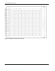
64 Node Fast Ethernet Expandable to 192 Nodes Point-to-Point Cabling Guide Table 13-1: Cable Label Nomenclature Symbol Description R Rack number S Control/Compute/Storage node number SW Out of Band (OOB) Management Switch/Cluster Interconnect Switch/In Band (IB) Management Switch number M Module letter or Module number P Port number NIC NIC port number iLO iLO port Table 13-2: 64 Node Fast Ethernet Cabling for DL360 LC Clusters Expandable to 192 Nodes OOB Switch Cabling Origin (server) Des
64 Node Fast Ethernet Expandable to 192 Nodes Table 13-2: 64 Node Fast Ethernet Cabling for DL360 LC Clusters Expandable to 192 Nodes continued OOB Switch Cabling Origin (server) Destination (switch) Cluster Interconnect Switch Cabling Origin (server) Destination (switch) IB Management Switch Cabling Origin (server) Destination (switch) R1-S14-ILO R1-SW2-P14 R1-S14-NIC2 R2-SW1-MC-P22 R1-S14-NIC1 R1-SW1-P14 R1-S15-ILO R1-SW2-P15 R1-S15-NIC2 R2-SW1-MC-P23 R1-S15-NIC1 R1-SW1-P15 R1-S16-ILO
64 Node Fast Ethernet Expandable to 192 Nodes Table 13-2: 64 Node Fast Ethernet Cabling for DL360 LC Clusters Expandable to 192 Nodes continued OOB Switch Cabling Origin (server) Destination (switch) Cluster Interconnect Switch Cabling Origin (server) Destination (switch) IB Management Switch Cabling Origin (server) Destination (switch) R2-S4-ILO R2-SW3-P4 R2-S4-NIC2 R2-SW1-MB-P4 R2-S4-NIC1 R2-SW2-P4 R2-S5-ILO R2-SW3-P5 R2-S5-NIC2 R2-SW1-MB-P5 R2-S5-NIC1 R2-SW2-P5 R2-S6-ILO R2-SW3-P6 R
64 Node Fast Ethernet Expandable to 192 Nodes Table 13-2: 64 Node Fast Ethernet Cabling for DL360 LC Clusters Expandable to 192 Nodes continued OOB Switch Cabling Origin (server) Destination (switch) Cluster Interconnect Switch Cabling Origin (server) Destination (switch) IB Management Switch Cabling Origin (server) Destination (switch) R3-S1-ILO R3-SW2-P1 R3-S1-NIC2 R2-SW1-ME-P1 R3-S1-NIC1 R3-SW1-P1 R3-S2-ILO R3-SW2-P2 R3-S2-NIC2 R2-SW1-ME-P2 R3-S2-NIC1 R3-SW1-P2 R3-S3-ILO R3-SW2-P3 R
64 Node Fast Ethernet Expandable to 192 Nodes Table 13-2: 64 Node Fast Ethernet Cabling for DL360 LC Clusters Expandable to 192 Nodes continued OOB Switch Cabling Origin (server) Destination (switch) Cluster Interconnect Switch Cabling Origin (server) Destination (switch) IB Management Switch Cabling Origin (server) Destination (switch) R3-S31-ILO R3-SW2-P31 R3-S31-NIC2 R2-SW1-MF-P7 R3-S31-NIC1 R3-SW1-P31 R3-S32-ILO R3-SW2-P32 R3-S32-NIC2 R2-SW1-MF-P8 R3-S32-NIC1 R3-SW1-P32 R3-S33-ILO R
64 Node Fast Ethernet Expandable to 192 Nodes Table 13-2: 64 Node Fast Ethernet Cabling for DL360 LC Clusters Expandable to 192 Nodes continued OOB Switch Cabling Origin (server) Destination (switch) Cluster Interconnect Switch Cabling Origin (server) Destination (switch) IB Management Switch Cabling Origin (server) Destination (switch) R4-S21-ILO R4-SW2-P21 R4-S21-NIC2 R2-SW1-MG-P13 R4-S21-NIC1 R4-SW1-P21 R4-S22-ILO R4-SW2-P22 R4-S22-NIC2 R2-SW1-MG-P14 R4-S22-NIC1 R4-SW1-P22 R4-S23-ILO
64 Node Fast Ethernet Expandable to 192 Nodes Table 13-2: 64 Node Fast Ethernet Cabling for DL360 LC Clusters Expandable to 192 Nodes continued OOB Switch Cabling Origin (server) Destination (switch) Cluster Interconnect Switch Cabling Origin (server) Destination (switch) IB Management Switch Cabling Origin (server) Destination (switch) R5-S11-ILO R5-SW2-P11 R5-S11-NIC2 R2-SW1-MH-P19 R5-S11-NIC1 R5-SW1-P11 R5-S12-ILO R5-SW2-P12 R5-S12-NIC2 R2-SW1-MH-P20 R5-S12-NIC1 R5-SW1-P12 R5-S13-ILO
64 Node Fast Ethernet Expandable to 192 Nodes Table 13-3: OOB Management Switch Uplink From To R1-SW2-P48 R1-SW1-P48 R2-SW3-P48 R2-SW2-P48 R3-SW2-P48 R3-SW1-P48 R4-SW2-P48 R4-SW1-P48 R5-SW2-P48 R5-SW1-P48 Table 13-4: IB Management Switch Uplink From 13-10 To R2-SW2-P47 R1-SW1-P50 R2-SW2-P46 R1-SW1-P49 R2-SW2-P45 R3-SW1-P50 R2-SW2-P44 R3-SW1-P49 R2-SW2-P43 R4-SW1-P50 R2-SW2-P42 R4-SW1-P49 R2-SW2-P41 R5-SW1-P50 R2-SW2-P40 R5-SW1-P49 Trunked together Trunked together Trunked t
A Cabling Rules for LC Clusters HP factory-configured LC clusters are built according to these guidelines for numbering, labeling, and populating LC clusters. The guidelines are included in this document as reference information for customers who are customizing or upgrading existing LC clusters. Numbering and Cable Labeling Rules Racks—Racks are numbered 1 to n and from left to right. The racks are labeled “Rack n,” where n is the rack number.
Cabling Rules for LC Clusters PCI Cards—Labels on cables connected to the PCI cards use the PCI slot markings on the server if available. The designator of the actual slot name is used on the labels, if present, or “PCIn” is used, where n is the slot number, if the slots are numbered. For example, if the hardware marks the slots with “1” or “2,” then the cable labels refer to these slots as “PCI1” and “PCI2,” respectively.
Cabling Rules for LC Clusters Power Connections—The factory distributes the power connections across the PDUs in the LC cluster to avoid overload conditions. The most common PDUs used in the LC clusters are the 24A and 32A Control Units with four, eight-receptacle Extension Bars. Using these PDUs, the factory will not connect more than five components to an Extension Bar and no more than 14 total components to each PDU. Different population rules may apply to different capacity PDUs.