
2424m Gigabit Stacking Module Installation Guide 1999-03


8
Installing the Module
If the Module Status, Self Test, and Fault LEDs are flashing, the
module may not be completely installed. Make sure the module is
installed all the way into the switch slot. If the flashing continues,
see the Troubleshooting section on page 13.
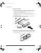
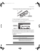
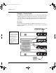
5. Connect the Network Cables
1. Connect the appropriate network cables to the module’s transceiver ports.
The table below shows the supported cable types for each of the trans-
ceivers.
Supported Cable Types.
Port Type Cable Type Length Limits
Gigabit-SX 62.5/125 µm or 50/125 µm core/cladding
diameter, graded-index, multimode
fiber-optic cables that are fitted with SC
connectors—the cables must comply
with the ITU-T G.651 and ISO,IEC 793-2
Type A1b or A1a standards.
• 62.5 µm cable:
– 160 MHz*km = 220 meters
– 200 MHz*km = 275 meters
• 50 µm cable:
– 400 MHz*km = 500 meters
– 500 MHz*km = 550 meters
Gigabit-LX single-mode cables fitted with SC
connectors—the cables must comply
with the ITU-T G.652 and ISO,IEC 793-2
Type B1 standards.
The multimode fiber-optic cable
specified for the Gigabit-SX port may
also be used for the Gigabit-LX port, but
a mode conditioning patch cord may be
needed — see “Mode Conditioning
Patch Cord for Gigabit-LX” on page 17
for more information.
• single-mode cable - 5 kilometers
• multimode cable - 550 meters
Gigabit
Stacking
Shielded twisted-pair cable supplied
with the Gigabit Stacking Kit (HP J4116A)
A 1/2-meter cable is included in the
Gigabit Stacking Kit.
A 10-meter cable has also been
tested and verified. The cable is
AMP part number 627124-1.
JRUGERRN3DJH7KXUVGD\0DUFK$0