
Brocade Converged Enhanced Ethernet Administrator's Guide v6.1.2_cee (53-1001258-01, June 2009)
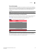
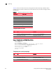
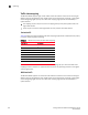
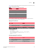


Table Of Contents
- Contents
- Figures
- Tables
- About This Document
- Introducing FCoE
- Using the CEE CLI
- In this chapter
- CEE CLI configuration guidelines and restrictions
- Using the CEE command line interface (CLI)
- CEE CLI RBAC permissions
- Accessing the CEE CLI through the console interface or through a Telnet session
- Accessing the CEE CLI from the Fabric OS shell
- Accessing CEE CLI command modes
- Using CEE CLI keyboard shortcuts
- Displaying CEE CLI commands and command syntax
- Using CEE CLI command completion
- CEE CLI command syntax conventions
- Using CEE CLI command output modifiers
- Configuring VLANs Using the CEE CLI
- In this chapter
- VLAN overview
- Ingress VLAN filtering
- VLAN configuration guidelines and restrictions
- Default VLAN configuration
- VLAN configuration procedures
- Enabling and disabling a CEE interface
- Configuring the MTU on a CEE interface
- Creating a VLAN interface
- Configuring a VLAN interface to forward FCoE traffic
- Configuring a CEE interface as a Layer 2 switch port
- Configuring a CEE interface as an access interface or a trunk interface
- Configuring VLAN classifier rules
- Configuring VLAN classifier groups
- Associating a VLAN classifier group to a CEE interface
- Clearing VLAN counter statistics
- Displaying VLAN information
- Configuring the MAC address table
- Configuring STP, RSTP, and MSTP using the CEE CLI
- In this chapter
- STP overview
- RSTP overview
- MSTP overview
- STP, RSTP, and MSTP configuration guidelines and restrictions
- Default STP, RSTP, and MSTP configuration
- STP, RSTP, and MSTP configuration procedures
- STP, RSTP, and MSTP-specific configuration procedures
- STP and RSTP-specific configuration procedures
- RSTP and MSTP-specific configuration procedures
- MSTP-specific configuration procedures
- 10-Gigabit Ethernet CEE interface-specific configuration
- Global STP, RSTP, and MSTP-related configuration procedures
- Clearing STP, RSTP, and MSTP-related information
- Displaying STP, RSTP, and MSTP-related information
- Configuring Link Aggregation using the CEE CLI
- Configuring LLDP using the CEE CLI
- Configuring ACLs using the CEE CLI
- In this chapter
- ACL overview
- Default ACL configuration
- ACL configuration guidelines and restrictions
- ACL configuration procedures
- Creating a standard MAC ACL and adding rules
- Creating an extended MAC ACL and adding rules
- Modifying a MAC ACL
- Removing a MAC ACL
- Reordering the sequence numbers in a MAC ACL
- Applying a MAC ACL to a CEE interface
- Applying a MAC ACL to a VLAN interface
- Clearing MAC ACL counters
- Displaying MAC ACL information
- Configuring QoS using the CEE CLI
- Configuring FCoE using the Fabric OS CLI
- Administering the switch
- Configuring RMON using the CEE CLI
- Index

112 Converged Enhanced Ethernet Administrator’s Guide
53-1001258-01
Congestion control
8
Ethernet pause
Ethernet Pause is an IEEE 802.3 standard mechanism for back pressuring a neighboring device.
Pause messages are sent by utilizing the optional MAC control sublayer. A Pause frame contains a
2-byte pause number, which states the length of the pause in units of 512 bit times. When a device
receives a Pause frame, it must stop sending any data on the interface for the specified length of
time, once it completes transmission of any frame in progress. You can use this feature to reduce
Ethernet packet losses by using a standardized mechanism. However the Pause mechanism does
not have the ability to selectively back pressure data sources multiple hops away, or exert any
control per VLAN or per priority so it is disruptive to all traffic on the link.
Ethernet Pause includes the following features:
• All configuration parameters can be specified independently per interface.
• Pause On/Off can be specified independently for TX and RX directions. No support is provided
for auto-negotiation.
• Pause generation is based on input (receive) queueing. Queue levels are tracked per input
port. You can change the high-water and low-water threshold for each input port. When the
instantaneous queue depth crosses the high-water mark then a Pause is generated. If any
additional packets are received and the queue length is still above the low-water mark then
additional Pause’s are generated. Once the queue length drops below the low-water mark then
Pause generation ceases.
• A Pause that is received and processed halts transmission of the output queues associated
with the port for the duration specified in the Pause frame.
Enabling an Ethernet Pause
Example of enabling an interface 802.3x Pause flow control TX and RX.
switch:admin>cmsh
switch>enable
switch#configure terminal
Enter configuration commands, one per line. End with CNTL/Z.
switch(config)#interface tengigabitethernet 0/2
switch(conf-if-te-0/2)#qos flowcontrol tx on rx on
switch(conf-if-te-0/2)#exit
switch(config)#exit
switch#
Step Task Command
1 Enter global configuration mode.
switch#configure terminal
2 Specify the 10-gigabit Ethernet interface. In
this example, 0/2 is used.
switch(config)#interface
tengigabitethernet 0/2
3 Enable an Ethernet Pause on the interface for
both TX and RX traffic.
switch(conf-if-te-0/2)#qos
flowcontrol tx on rx on