
Brocade Converged Enhanced Ethernet Administrator's Guide v6.1.2_cee (53-1001258-01, June 2009)
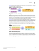
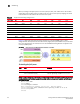
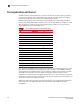
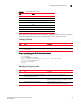
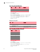
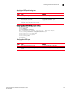

Table Of Contents
- Contents
- Figures
- Tables
- About This Document
- Introducing FCoE
- Using the CEE CLI
- In this chapter
- CEE CLI configuration guidelines and restrictions
- Using the CEE command line interface (CLI)
- CEE CLI RBAC permissions
- Accessing the CEE CLI through the console interface or through a Telnet session
- Accessing the CEE CLI from the Fabric OS shell
- Accessing CEE CLI command modes
- Using CEE CLI keyboard shortcuts
- Displaying CEE CLI commands and command syntax
- Using CEE CLI command completion
- CEE CLI command syntax conventions
- Using CEE CLI command output modifiers
- Configuring VLANs Using the CEE CLI
- In this chapter
- VLAN overview
- Ingress VLAN filtering
- VLAN configuration guidelines and restrictions
- Default VLAN configuration
- VLAN configuration procedures
- Enabling and disabling a CEE interface
- Configuring the MTU on a CEE interface
- Creating a VLAN interface
- Configuring a VLAN interface to forward FCoE traffic
- Configuring a CEE interface as a Layer 2 switch port
- Configuring a CEE interface as an access interface or a trunk interface
- Configuring VLAN classifier rules
- Configuring VLAN classifier groups
- Associating a VLAN classifier group to a CEE interface
- Clearing VLAN counter statistics
- Displaying VLAN information
- Configuring the MAC address table
- Configuring STP, RSTP, and MSTP using the CEE CLI
- In this chapter
- STP overview
- RSTP overview
- MSTP overview
- STP, RSTP, and MSTP configuration guidelines and restrictions
- Default STP, RSTP, and MSTP configuration
- STP, RSTP, and MSTP configuration procedures
- STP, RSTP, and MSTP-specific configuration procedures
- STP and RSTP-specific configuration procedures
- RSTP and MSTP-specific configuration procedures
- MSTP-specific configuration procedures
- 10-Gigabit Ethernet CEE interface-specific configuration
- Global STP, RSTP, and MSTP-related configuration procedures
- Clearing STP, RSTP, and MSTP-related information
- Displaying STP, RSTP, and MSTP-related information
- Configuring Link Aggregation using the CEE CLI
- Configuring LLDP using the CEE CLI
- Configuring ACLs using the CEE CLI
- In this chapter
- ACL overview
- Default ACL configuration
- ACL configuration guidelines and restrictions
- ACL configuration procedures
- Creating a standard MAC ACL and adding rules
- Creating an extended MAC ACL and adding rules
- Modifying a MAC ACL
- Removing a MAC ACL
- Reordering the sequence numbers in a MAC ACL
- Applying a MAC ACL to a CEE interface
- Applying a MAC ACL to a VLAN interface
- Clearing MAC ACL counters
- Displaying MAC ACL information
- Configuring QoS using the CEE CLI
- Configuring FCoE using the Fabric OS CLI
- Administering the switch
- Configuring RMON using the CEE CLI
- Index
Converged Enhanced Ethernet Administrator’s Guide 115
53-1001258-01
Scheduling
8
Figure 9 shows the packet scheduling order for a SP scheduler servicing two SP queues. The higher
numbered queue, SP2, has a higher priority.
FIGURE 9 Strict priority schedule — two queues
Weighted round robin scheduling
Weighted round robin scheduling is used to facilitate controlled sharing of the network bandwidth.
WRR assigns a weight to each queue; that value is then used to determine the amount of
bandwidth allocated to the queue. The round robin aspect of the scheduling allows each queue to
be serviced in a set ordering, sending a limited amount of data before moving onto the next queue
and cycling back to the highest priority queue after the lowest priority is serviced.
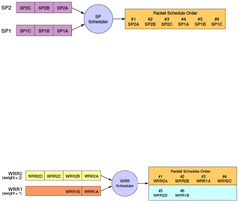
Figure 10 shows the packet scheduling order for a WRR scheduler servicing two WRR queues. The
higher numbered queue is considered higher priority (WRR2) and the weights indicate the network
bandwidth should be allocated in a 2:1 ratio between the two queues. In Figure 10 WRR2 should
receive 66% of bandwidth and WRR1 receives 33%. The WRR scheduler tracks the extra
bandwidth used and subtracts it from the bandwidth allocation for the next cycle through the
queues. In this the bandwidth utilization statistically matches the queue weights over longer time
periods.
FIGURE 10 WRR schedule — two queues
Traffic class scheduling policy
The traffic classes are numbered from 0 to 7; higher numbered traffic classes are considered
higher priority. The Brocade 8000 provides full flexibility in controlling the number of SP-to-WRR
queues. The number of SP queues is specified in N (SP1 through 8), then the highest priority traffic
classes are configured for SP service and the remaining 8 are WRR serviced. Table 20 shows the
set of scheduling configurations supported.