
Brocade Converged Enhanced Ethernet Administrator's Guide v6.1.2_cee (53-1001258-01, June 2009)
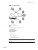
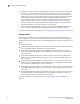
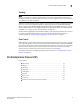
Table Of Contents
- Contents
- Figures
- Tables
- About This Document
- Introducing FCoE
- Using the CEE CLI
- In this chapter
- CEE CLI configuration guidelines and restrictions
- Using the CEE command line interface (CLI)
- CEE CLI RBAC permissions
- Accessing the CEE CLI through the console interface or through a Telnet session
- Accessing the CEE CLI from the Fabric OS shell
- Accessing CEE CLI command modes
- Using CEE CLI keyboard shortcuts
- Displaying CEE CLI commands and command syntax
- Using CEE CLI command completion
- CEE CLI command syntax conventions
- Using CEE CLI command output modifiers
- Configuring VLANs Using the CEE CLI
- In this chapter
- VLAN overview
- Ingress VLAN filtering
- VLAN configuration guidelines and restrictions
- Default VLAN configuration
- VLAN configuration procedures
- Enabling and disabling a CEE interface
- Configuring the MTU on a CEE interface
- Creating a VLAN interface
- Configuring a VLAN interface to forward FCoE traffic
- Configuring a CEE interface as a Layer 2 switch port
- Configuring a CEE interface as an access interface or a trunk interface
- Configuring VLAN classifier rules
- Configuring VLAN classifier groups
- Associating a VLAN classifier group to a CEE interface
- Clearing VLAN counter statistics
- Displaying VLAN information
- Configuring the MAC address table
- Configuring STP, RSTP, and MSTP using the CEE CLI
- In this chapter
- STP overview
- RSTP overview
- MSTP overview
- STP, RSTP, and MSTP configuration guidelines and restrictions
- Default STP, RSTP, and MSTP configuration
- STP, RSTP, and MSTP configuration procedures
- STP, RSTP, and MSTP-specific configuration procedures
- STP and RSTP-specific configuration procedures
- RSTP and MSTP-specific configuration procedures
- MSTP-specific configuration procedures
- 10-Gigabit Ethernet CEE interface-specific configuration
- Global STP, RSTP, and MSTP-related configuration procedures
- Clearing STP, RSTP, and MSTP-related information
- Displaying STP, RSTP, and MSTP-related information
- Configuring Link Aggregation using the CEE CLI
- Configuring LLDP using the CEE CLI
- Configuring ACLs using the CEE CLI
- In this chapter
- ACL overview
- Default ACL configuration
- ACL configuration guidelines and restrictions
- ACL configuration procedures
- Creating a standard MAC ACL and adding rules
- Creating an extended MAC ACL and adding rules
- Modifying a MAC ACL
- Removing a MAC ACL
- Reordering the sequence numbers in a MAC ACL
- Applying a MAC ACL to a CEE interface
- Applying a MAC ACL to a VLAN interface
- Clearing MAC ACL counters
- Displaying MAC ACL information
- Configuring QoS using the CEE CLI
- Configuring FCoE using the Fabric OS CLI
- Administering the switch
- Configuring RMON using the CEE CLI
- Index
Converged Enhanced Ethernet Administrator’s Guide 5
53-1001258-01
Layer 2 Ethernet overview
1
FIGURE 2 Brocade 8000 CEE switch logical view
The FCoE VF_ports provide FC services to FCoE initiators and targets, as well as an FCoE-to-FC
bridging service that allows FCoE initiators to access FC targets and conversely, allows FC targets to
access FCoE initiators.
Brocade's implementation of FCoE for the Brocade 8000 CEE switch provides integral N_port ID
virtualization (NPIV) support. Multiple VN_port devices can log in to a single FCoE VF_port
interface. Up to 1,000 VN_port devices can log in to a single Brocade 8000 CEE switch.
Each of the embedded FCoE ports supports four logical traffic paths. These four logical traffic
paths share the FCoE port bandwidth. Any single traffic path may use the entire 10-Gbps of FCoE
port bandwidth if available, but it must share the bandwidth equally with the other logical path
traffic flows if more than one is active. The bandwidth available to any single logical traffic path
(and therefore any single FCoE-to-FC traffic flow) is between 2.5 Gbps and 10 Gbps.
While they share the FCoE port bandwidth, the logical traffic paths are independent from one
another in the event of downstream congestion. If the traffic flowing on one logical path stalls
because of congestion, the traffic flowing on the other logical paths on the same FCoE port is not
affected. Note however, that a logical traffic path is not limited to a single FCoE-to-FC traffic flow. If
multiple traffic flows are sharing the same logical traffic path, congestion independence between
the flows cannot be enforced.
Layer 2 Ethernet overview
In this section:
•Layer 2 forwarding . . . . . . . . . . . . . . . . . . . . . . . . . . . . . . . . . . . . . . . . . . . . . . . 6
•VLAN tagging . . . . . . . . . . . . . . . . . . . . . . . . . . . . . . . . . . . . . . . . . . . . . . . . . . . 7
•Loop-free network environment . . . . . . . . . . . . . . . . . . . . . . . . . . . . . . . . . . . . 7
•Frame classification (incoming) . . . . . . . . . . . . . . . . . . . . . . . . . . . . . . . . . . . . 8
•Congestion control and queuing. . . . . . . . . . . . . . . . . . . . . . . . . . . . . . . . . . . . 8
•Access control . . . . . . . . . . . . . . . . . . . . . . . . . . . . . . . . . . . . . . . . . . . . . . . . . 10
•Trunking . . . . . . . . . . . . . . . . . . . . . . . . . . . . . . . . . . . . . . . . . . . . . . . . . . . . . . 11
•Flow Control . . . . . . . . . . . . . . . . . . . . . . . . . . . . . . . . . . . . . . . . . . . . . . . . . . . 11
Ethernet Switch
Six embedded
10-Gigabit
FCoE ports
24 10-Gigabit
Ethernet
CEE ports
Eight 8-Gigabit
FC ports
FC Switch