
Brocade Converged Enhanced Ethernet Administrator's Guide v6.1.2_cee (53-1001258-01, June 2009)
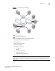
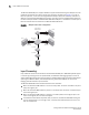
Table Of Contents
- Contents
- Figures
- Tables
- About This Document
- Introducing FCoE
- Using the CEE CLI
- In this chapter
- CEE CLI configuration guidelines and restrictions
- Using the CEE command line interface (CLI)
- CEE CLI RBAC permissions
- Accessing the CEE CLI through the console interface or through a Telnet session
- Accessing the CEE CLI from the Fabric OS shell
- Accessing CEE CLI command modes
- Using CEE CLI keyboard shortcuts
- Displaying CEE CLI commands and command syntax
- Using CEE CLI command completion
- CEE CLI command syntax conventions
- Using CEE CLI command output modifiers
- Configuring VLANs Using the CEE CLI
- In this chapter
- VLAN overview
- Ingress VLAN filtering
- VLAN configuration guidelines and restrictions
- Default VLAN configuration
- VLAN configuration procedures
- Enabling and disabling a CEE interface
- Configuring the MTU on a CEE interface
- Creating a VLAN interface
- Configuring a VLAN interface to forward FCoE traffic
- Configuring a CEE interface as a Layer 2 switch port
- Configuring a CEE interface as an access interface or a trunk interface
- Configuring VLAN classifier rules
- Configuring VLAN classifier groups
- Associating a VLAN classifier group to a CEE interface
- Clearing VLAN counter statistics
- Displaying VLAN information
- Configuring the MAC address table
- Configuring STP, RSTP, and MSTP using the CEE CLI
- In this chapter
- STP overview
- RSTP overview
- MSTP overview
- STP, RSTP, and MSTP configuration guidelines and restrictions
- Default STP, RSTP, and MSTP configuration
- STP, RSTP, and MSTP configuration procedures
- STP, RSTP, and MSTP-specific configuration procedures
- STP and RSTP-specific configuration procedures
- RSTP and MSTP-specific configuration procedures
- MSTP-specific configuration procedures
- 10-Gigabit Ethernet CEE interface-specific configuration
- Global STP, RSTP, and MSTP-related configuration procedures
- Clearing STP, RSTP, and MSTP-related information
- Displaying STP, RSTP, and MSTP-related information
- Configuring Link Aggregation using the CEE CLI
- Configuring LLDP using the CEE CLI
- Configuring ACLs using the CEE CLI
- In this chapter
- ACL overview
- Default ACL configuration
- ACL configuration guidelines and restrictions
- ACL configuration procedures
- Creating a standard MAC ACL and adding rules
- Creating an extended MAC ACL and adding rules
- Modifying a MAC ACL
- Removing a MAC ACL
- Reordering the sequence numbers in a MAC ACL
- Applying a MAC ACL to a CEE interface
- Applying a MAC ACL to a VLAN interface
- Clearing MAC ACL counters
- Displaying MAC ACL information
- Configuring QoS using the CEE CLI
- Configuring FCoE using the Fabric OS CLI
- Administering the switch
- Configuring RMON using the CEE CLI
- Index
8 Converged Enhanced Ethernet Administrator’s Guide
53-1001258-01
Layer 2 Ethernet overview
1
• Multiple Spanning Tree Protocol (MSTP)—MSTP defines an extension to RSTP to further develop
the usefulness of VLANs. With per-VLAN MSTP, you can configure a separate spanning tree for
each VLAN group and block the links that are redundant in each spanning tree. Using MSTP,
you can create multiple loop-free active topologies on a single physical topology. These
loop-free topologies are mapped to a set of configurable VLANs. This enables you to better
utilize the physical resources present in the network and achieve better load balancing of VLAN
traffic.
For detailed information on configuring these protocols, see “Configuring STP, RSTP, and MSTP
using the CEE CLI” on page 39.
Frame classification (incoming)
The Brocade 8000 CEE switch is capable of classifying incoming Ethernet frames based on the
following criteria:
• Port number
• Protocol
• MAC address
The classified frames can be tagged with a VLAN ID or with 802.1p Ethernet priority. The 802.1p
Ethernet priority tagging is done using the Layer 2 Class of Service (CoS). The 802.1p Ethernet
priority is used to tag frames in a VLAN with a Layer 2 CoS to prioritize traffic in the VLAN. The
Brocade 8000 CEE switch also accepts frames that have been tagged by an external device.
Frame classification options are as follows:
• VLAN ID and Layer 2 CoS by physical port number—With this option, the port is set to classify
incoming frames to a preset VLAN ID and the Layer 2 CoS by the physical port number on the
Brocade 8000 CEE switch.
• VLAN ID and Layer 2 CoS by LAG virtual port number—With this option, the port is set to classify
incoming frames to a preset VLAN ID and Layer 2 CoS by the Link Aggregation Group (LAG)
virtual port number.
• Layer 2 CoS mutation—With this option, the port is set to change the Layer 2 CoS setting by
enabling the QoS mutation feature.
• Layer 2 CoS trust—With this option, the port is set to accept the Layer 2 CoS of incoming
frames by enabling the QoS trust feature.
For detailed information on configuring QoS, see “Configuring QoS using the CEE CLI” on page 103.
Congestion control and queuing
The Brocade 8000 CEE switch supports several congestion control and queuing strategies. As an
output queue approaches congestion, Random Early Detection (RED) is used to selectively and
proactively drop frames to maintain maximum link utilization. Incoming frames are classified into
priority queues based on the Layer 2 CoS or IP Type of Service (TOS) setting of the incoming frame,
or the possible rewriting of the Layer 2 CoS field based on the settings of the Brocade 8000 CEE
port or VLAN.
The Brocade 8000 CEE switch supports a combination of two scheduling strategies to queue
frames to the egress ports: Priority queuing, which is also referred to as strict priority, and Deficit
Weighted Round Robin (DWRR) queuing. The scheduling algorithms work on the eight traffic
classes as specified in 802.1Qaz Enhanced Transmission Selection (ETS).