
Brocade Converged Enhanced Ethernet Administrator's Guide v6.1.2_cee (53-1001258-01, June 2009)
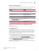

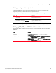
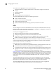
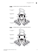
Table Of Contents
- Contents
- Figures
- Tables
- About This Document
- Introducing FCoE
- Using the CEE CLI
- In this chapter
- CEE CLI configuration guidelines and restrictions
- Using the CEE command line interface (CLI)
- CEE CLI RBAC permissions
- Accessing the CEE CLI through the console interface or through a Telnet session
- Accessing the CEE CLI from the Fabric OS shell
- Accessing CEE CLI command modes
- Using CEE CLI keyboard shortcuts
- Displaying CEE CLI commands and command syntax
- Using CEE CLI command completion
- CEE CLI command syntax conventions
- Using CEE CLI command output modifiers
- Configuring VLANs Using the CEE CLI
- In this chapter
- VLAN overview
- Ingress VLAN filtering
- VLAN configuration guidelines and restrictions
- Default VLAN configuration
- VLAN configuration procedures
- Enabling and disabling a CEE interface
- Configuring the MTU on a CEE interface
- Creating a VLAN interface
- Configuring a VLAN interface to forward FCoE traffic
- Configuring a CEE interface as a Layer 2 switch port
- Configuring a CEE interface as an access interface or a trunk interface
- Configuring VLAN classifier rules
- Configuring VLAN classifier groups
- Associating a VLAN classifier group to a CEE interface
- Clearing VLAN counter statistics
- Displaying VLAN information
- Configuring the MAC address table
- Configuring STP, RSTP, and MSTP using the CEE CLI
- In this chapter
- STP overview
- RSTP overview
- MSTP overview
- STP, RSTP, and MSTP configuration guidelines and restrictions
- Default STP, RSTP, and MSTP configuration
- STP, RSTP, and MSTP configuration procedures
- STP, RSTP, and MSTP-specific configuration procedures
- STP and RSTP-specific configuration procedures
- RSTP and MSTP-specific configuration procedures
- MSTP-specific configuration procedures
- 10-Gigabit Ethernet CEE interface-specific configuration
- Global STP, RSTP, and MSTP-related configuration procedures
- Clearing STP, RSTP, and MSTP-related information
- Displaying STP, RSTP, and MSTP-related information
- Configuring Link Aggregation using the CEE CLI
- Configuring LLDP using the CEE CLI
- Configuring ACLs using the CEE CLI
- In this chapter
- ACL overview
- Default ACL configuration
- ACL configuration guidelines and restrictions
- ACL configuration procedures
- Creating a standard MAC ACL and adding rules
- Creating an extended MAC ACL and adding rules
- Modifying a MAC ACL
- Removing a MAC ACL
- Reordering the sequence numbers in a MAC ACL
- Applying a MAC ACL to a CEE interface
- Applying a MAC ACL to a VLAN interface
- Clearing MAC ACL counters
- Displaying MAC ACL information
- Configuring QoS using the CEE CLI
- Configuring FCoE using the Fabric OS CLI
- Administering the switch
- Configuring RMON using the CEE CLI
- Index
68 Converged Enhanced Ethernet Administrator’s Guide
53-1001258-01
Link aggregation overview
5
The benefits of link aggregation are summarized as follows:
• Increased bandwidth. The logical bandwidth can be dynamically changed as the demand
changes.
• Increased availability.
• Load sharing.
• Rapid configuration and reconfiguration.
The Brocade 8000 CEE switch supports the following trunk types:
• Static, standards-based LAG.
• Dynamic, standards-based LAG using LACP.
• Static, Brocade-proprietary LAG.
• Dynamic, Brocade-proprietary LAG using proprietary enhancements to LACP.
LAGs
You can configure a maximum of 24 LAGs with up to 16 links per standard LAG and four links per
Brocade-proprietary LAG. Each LAG is associated with an aggregator. The aggregator manages the
Ethernet frame collection and distribution functions.
On each port, link aggregation control:
• Maintains configuration information to control port aggregation.
• Exchanges configuration information with other devices to form LAGs.
• Attaches ports to and detaches ports from the aggregator when they join or leave a LAG.
• Enables or disables an aggregator’s frame collection and distribution functions.
Each link in the Brocade 8000 CEE switch can be associated to a LAG; a link cannot be associated
to more than one LAG. The process of adding and removing links to and from a LAG is controlled
either statically, dynamically, or through LACP.
Each LAG consists of the following components:
• A MAC address that is different from the MAC addresses of the LAG’s individual member links.
• An interface index for each link to identify the link to neighboring devices.
• An administrative key for each link. Only links having the same administrative key value can be
aggregated into a LAG. On each link configured to use LACP, LACP automatically configures an
administrative key value equal to the port-channel identification number.
Figure 6 and Figure 7 show typical IP SAN configurations using LAGs. In a data center the Brocade
8000 CEE switch fits into the top-of-the-rack use case where all the servers in a rack are connected
to the Brocade 8000 CEE switch through Twinax copper or optical fiber cable. The database server
layer connects to the top-of-the-rack Brocade 8000 CEE switch which is located in the network
access layer.
The Brocade 8000 CEE switch connects to Layer 2/Layer 3 aggregation routers which provide
access into the existing LAN. This connectivity is formed in a standard V-design or square-design.
Both designs use the LAG as the uplink to provide redundancy and improved bandwidth.
The Brocade 8000 CEE switch interoperates with all of the major Layer 2/Layer 3 aggregation
routers including Foundry Networks, Cisco Systems, and Force10 Networks.